After nearly 1,000 miles on bowtie6 since the ECOTEC conversion, I have a ton of stuff to detail out. This is where you spend tons of time for little to show for. Sure, I could just leave it “as is”, but there is no fun in that. Sweating the details is what sets my car apart from all others.
Today, I spent some hours refining things in the main fuse box under the hood. I’m not 100% done with it yet, but I figured I’d take a few pictures of it so far and write about it. Maybe somebody might get some inspiration from all this work.
This is what the main engine-compartment fuse box looks like…

Big deal, huh? Well the silver box is located in the area where the windshield washer bottle used to be and also the area where the dealer-installed air conditioning system was installed. What is so special about this? Well other than the fact this is all hand-made aluminium, take a look at what is inside the box…

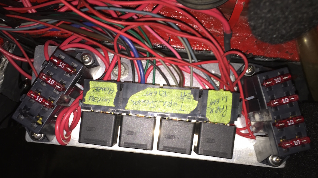
Now it gets interesting…
- Starting at the bottom of the picture are six circuit breakers. Today, I added the little red “booties” to prevent any short circuits. The middle breaker shows what they look like under the red “bootie”. Two terminals stick out and this is what the “booties” protect. Don’t want any electrical short circuits to happen here!
- Above the circuit breakers are seven relays. They control the most important basic functions underneath the hood.
- Above that towards the right is a fuse panel with 8 modern spade type fuses. These are used on the control side of the relays. Basically they make the electromagnets in the relays trip when a switch makes ground.
- The finned box with the three big connectors is the Engine Control Module (ECM) running the show on the ECOTEC. This is “factory” supplied from the donor engine.
- To the left of the ECM is the solid state electric fan controller.
Circuit Breakers
These guys act as fuses. They feed the hard voltage from the B+ terminal through the firewall to the relays. What B+ terminal? Since the battery is located in the trunk, we ran a welding-machine cable from the battery’s B+ terminal through the firewall by means of an insulated bolt. This is where we get voltage to the underhood fuse box and also to the inside of the cab (on the inside side of the bolt)
This is a close up of what this all looks like:

At the very left you see the post where full B+ voltage is supplied to the circuit breakers. The body and frame is ground so how does this keep from shorting out? The bolt is fully enclosed in a phenolic ring thus insulating the terminal. On one side of the circuit breakers is the hot B+ terminal – this is the one nearest to the camera. On the other terminal is the supply of power to the relays shown above. On the middle of each circuit breaker you can see the little black dot that acts as a “reset” button. I used circuit breakers because these are 100% essential to the electrical operation of the system. If they trip a simple push of the black “reset” button has me back in business.
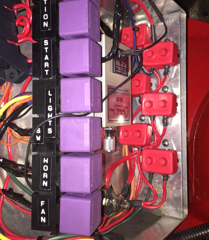
Relays
Seven relays run the show for the main switched hot lead, ECM, headlights switch, high/low beam, electric fan, horn, starter and ignition switch. All the switches on bowtie6 break ground. There is no hard voltage going through any switches. The advantage of this is longevity.
So basically when a switch is activated, it “makes” ground. This in turn causes the electromagnet in the relay to trip and that makes the circuit hot. There is no hard voltage through any switch except for one: ignition. I am using an industrial strength switch for this, rated for much higher amperage than what the Optima battery delivers. This will last past my lifetime.
Fuses
There are 8 fuses under the hood. These supply power to the control side of the relays as well as to the ECM and the electric fan controller. I used modern style fuse housings and bladed fuses. Glass fuses are just too poorly made and prone to failure and that makes them very unreliable. Not acceptable for bowtie6.
ECM and Engine Harness
The “brains” controlling the ECOTEC is the GM factory E67 ECM. The wiring from the ECM to the multitude of sensors on the ECOTEC is basically a factory harness from a Chevy HHR, modified to act as a Pontiac Solstice. We modified the harness by changing pin-outs and removing unnecessary circuits. This makes the harness much simpler to work with. Furthermore we cut many wires to make them shorter or longer depending on where they were located. This is the beauty of doing it “yourself” as opposed to buying something. Anybody can “buy” stuff… It takes talent to make you own.
Like I said before, the harness came from an HHR. GM went through a lot of work in making a very durable and well engineered harness. In my opinion, the quality of the wire is superb and the connectors are not only expensive but of very high quality. The harness is basically divided into three “plugs” (you can see them in the picture above). One has 56 pins; the other two have 73 pins. Not all are needed though and having a Factory Service Manual will be instrumental in determining what circuits are kept and which need to go.
To make the ECM work outside of the “factory” setup, one must remove the VATS. This is the “Vehicle Anti-Theft System”. You do this either sending the ECM out to somebody or by using a software package such as HP Tuners. We used HP Tuners. This also enabled us to tune the ECM.
Speaking of the ECM: make sure you get the right one. The ECM’s come in two varieties depending upon the type of gearbox used. An automatic gearbox ECM will not work on a 5 speed gearbox. Also, there are certain E67’s that will just won’t work. You will need to make sure you get the one with the right OS, otherwise it won’t work. This is why it is very important to get the ECM that came from the donor vehicle.
Solid State Fan Controller
This little device is trick. It has a built in relay and has B+, ground and a wire hooked up to the temp sensor on the block. This is where the device gets its temp signal. Here is the beauty of this device: on 99.99% of all street rods I see, folks stick a nasty looking probe in the middle of the radiator core. This not only looks awful but eventually wears a spot in the radiator’s core causing it to leak. I think this way to wire a controller not only looks crappy as hell but is very sloppy. The controller we use is not cheap, but it has a fully adjustable rotary knob that enables setting the proper temp to kick the fan on. In the photo above the controller sits on top of the ECM but I am planning to move it to a different location to make it look a little more elegant. Again, it is the details that count!
In Summary
I realize this is not everybody’s cup of tea (a polite way of saying “I don’t like it”) but once again this works for me and the car has been built to suit me not anyone else. I wired the thing, I know each circuit and quite frankly I am proud to say it is bullet proof. I blew a fuse one time, but that was my dumbass-self making a mistake. Again, one can source a ready made wiring harness but what do you learn by doing that? I spent a lot of time learning about circuits and how relays, fuses and circuit breakers work. This takes time but the result is very rewarding.
If you do decide to undertake something like this, there are a few things I would highly recommend:
- Every single terminal (and there are many) is soldered – nothing just crimped. This is extremely time consuming but worth every moment you spend on it. Soldering ensures a perfect connection and if you are going to spend this much time, you want it to be dead-nuts-accurate.
- I used the expensive shrink wrap that has the sticky stuff inside of it on every joint, every terminal and every splice. Why? This makes the connection water and moisture proof.
- Anytime I had to join parts of the harness, I used Weather Pack connectors. They are not cheap, take a long time to crimp and assemble but they are water and moisture proof and last forever. This is the only way to go. By doing the harness this way you can ensure certain parts can be take apart without removing the whole shebang. There is a bit of strategy to play here but you will be very happy with the result.
- I spent quite a bit of resources on only the best quality wire. All my wire came from an industrial supplier, not from a home-improvement store. This is industrial strength. The real-deal. I did this the first time with the V6 and it lasted flawlessly for 5 years. This time around I expect it to last much longer since we are braking ground instead of switching hard voltage.
- Relays – buy only the best (mine are Bosch) and don’t be stingy. Relays are the way to go. Once you get the basic principle of how they work they are fantastic. This folks, is not rocket science and is not black magic. Relays work and if you do it right, they last forever.
- Use the proper tools. I say again: use the proper tools I used good quality nippers, soldering gun, heat gun and crimping pliers. The Weather Pack connectors require a special crimper. Use the best you can afford. Otherwise you will have crappy connectors and this will lead to electrical problems and the dreaded “Lucas Syndrome” where wiring turns into very expensive blue smoke.
I could write about this forever but then again, I would bore the hell out of you. If you have any specific questions let me know and I can address them in a separate post.
Go do some wiring! It is not as complicated as the harness “makers” make you believe it is… 🙂
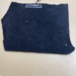
 The factory Triumph TR6 courtesy light is originally installed on a plinth, mounted on the driveshaft tunnel cover between the seats, toward the back. Unfortunately, the new driveshaft cover in bowtie6 is different from the original and the plinth does not fit so well.
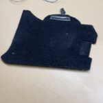
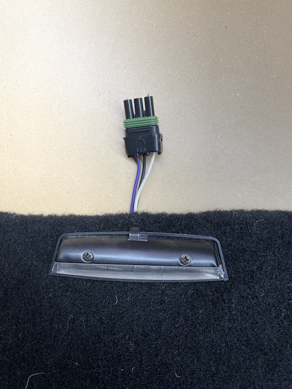
 I wired up the circuit and voila, after a few tries, got it working…
 You can see in the photo above, the terminals, my buggered up wiring and the two lights in action. Job done!
 Duh! After scratching my head a little, all it took was a few tests with my multimeter and now I have the proper wiring on paper.