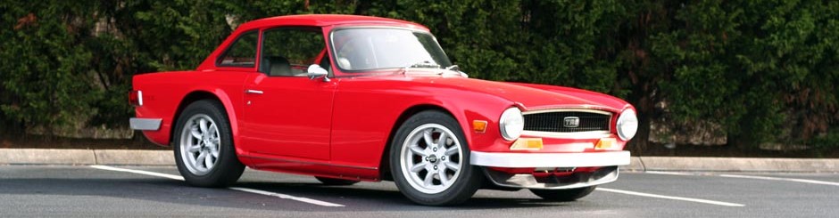
The other day I received a question about the bumpers on bowtie6 so I thought it might be of interest to explore the alternate solution I took regarding Triumph TR6 bumpers. As you can see from the featured image above, bowtie6‘s bumpers are not exactly “factory”. 😉
First Some History
When I originally purchased bowtie6, the original bumpers were part of the deal (if you want to see what they look like, see this gallery on my original website). However, they were in very poor shape: rusted, pitted and dinged up – not very attractive. I did some research on what it would take to “restore” them and quickly discovered this would not be for me, To have the bumpers chromed would be too expensive, the “chrome” look was not for me, and most important, they were way too heavy.
We thought about giving bowtie6 a “commando” look without bumpers. Something similar to what I did on my old Spitfire (pretty cool, huh?) The problem with that was a TR6 looks plain ugly without some sort of bumpers fore and aft.
Another option would have been to go with the stainless steel bumpers now available on the Interwebs. However, when I worked on restoring bowtie6 the stainless bumpers were not available and they too are too pricey.
The Solution – Bespoke Lightweight Triumph TR6 Bumpers
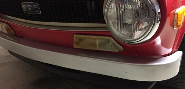
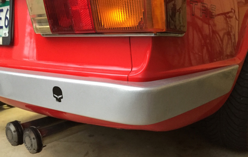
And so, after many hours of design my cousin Jim came up with this design for the bumpers and this is what the front bumpers look like:
-
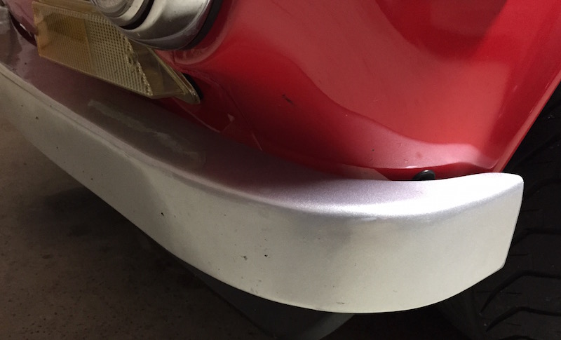
- Front bumper
-
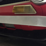
- Front bumper side closeup
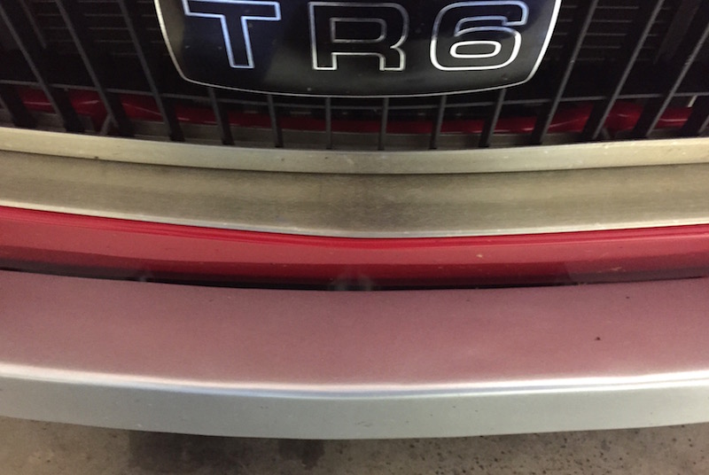
The rear bumper looks like this:
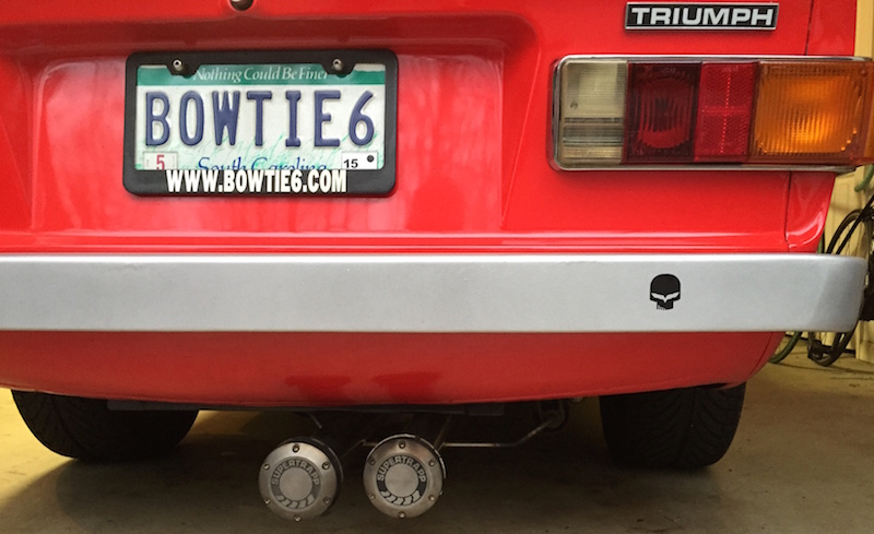
-
- Rear bumper detail
The bumpers are very simple and extremely lightweight, perhaps fragile. They are a “U-shaped” affair, painstakingly shaped and finished smooth. The finished bumpers were powder coated with a matte silver finish.
So How Were the Bumpers Made?
We worked on the basic shape using the original bumpers as a starting point and made cardboard templates. The templates were then transferred to sheets of aluminum and cut with shears. What we ended up at this point was an “L” shaped form. The top “lip” was then shrunk with a mechanical shrinking machine.
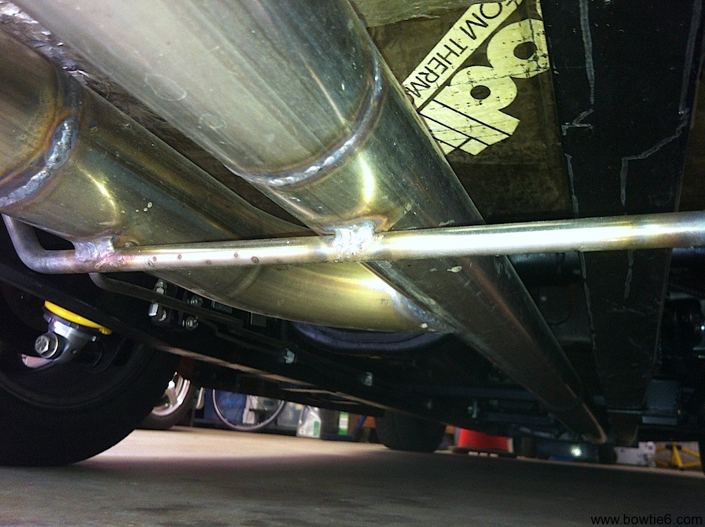
Now, before you start calling bullshit on me here, just keep in mind all this cannot be made in one piece! The bumpers as a whole are one unit, however they consist of several smaller sections TIG welded together. The welds were then hammered and filed smooth. This took patience and effort to pull off. Take a look at the following picture…
Shrink and weld marks are visible in this picture
This is the front bumper seen from below. To orient yourself, note the lower radiator intake on the extreme left. If you open this picture and look closely, you can see the shrinking machine marks, hammer marks and welding seams.
Mounting the bumpers to the body is very simple: they bolt straight up to the body panels with a rubber “washer” between the body and the tabs on the bumpers with stainless bolts. This is all achievable because these bumpers are feather light. All the factory bumper bracing that tie the back of the fender to the frame are not used. They are too heavy!
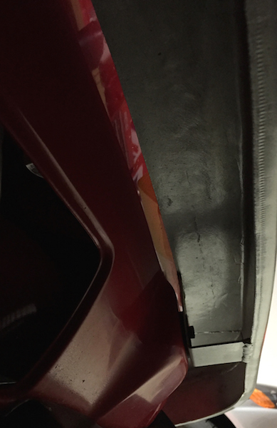
Here is another view of the front bumper from below (you can see the front spoiler):
Closeup of the mounting tab holding the bumper against the body
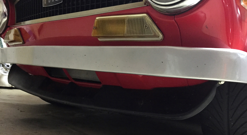
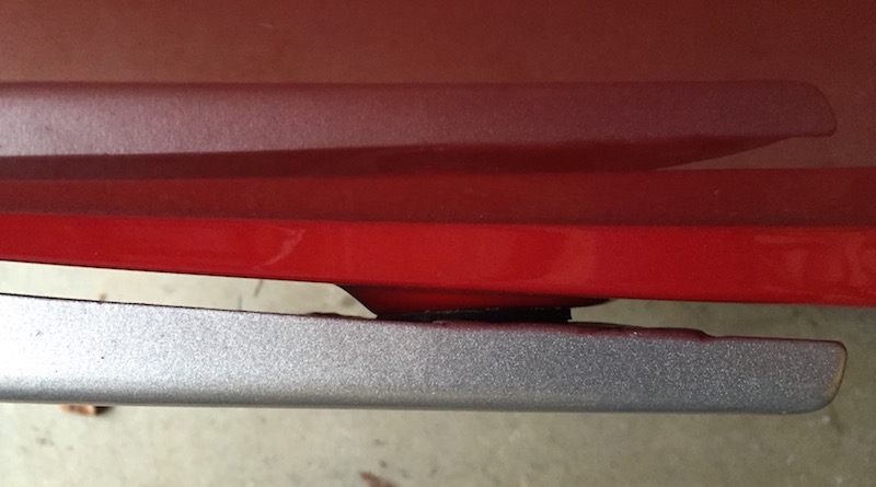
This picture shows the close tolerance between the bumper and the front nose. We tried to make this as close as possible so it would give a nice finished look. Pay close attention here because you can also see the custom aluminum finishing strip on the radiator intake as well as the grill surround. These were made using the same technique as the bumpers – they are all aluminum shaped by a shrinking machine.
Very close spacing tolerance between the bumper and body
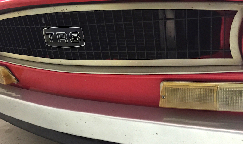
Front grille surround and finishing strip
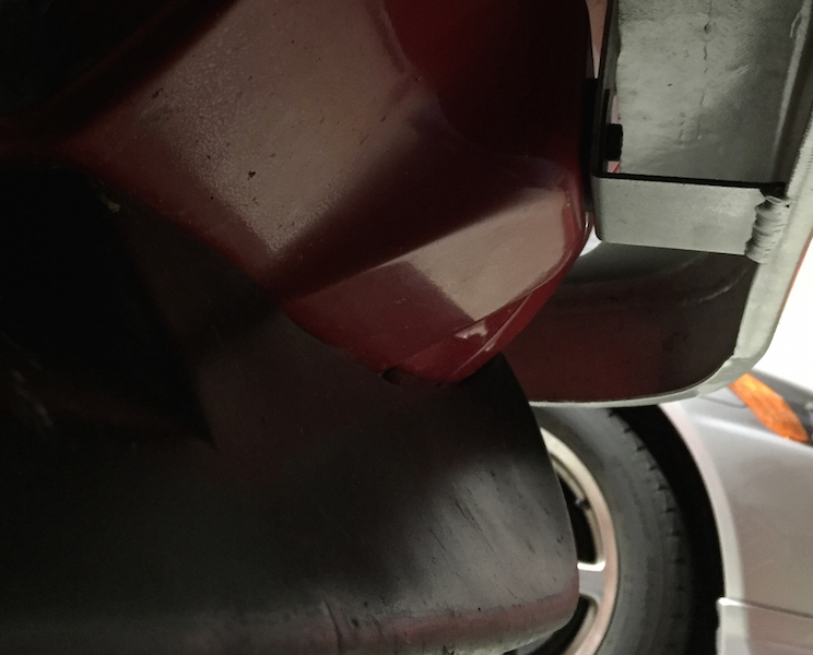
And now, here are some pictures of the rear bumper.
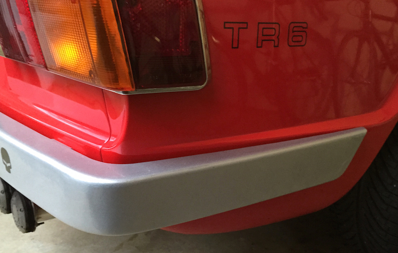
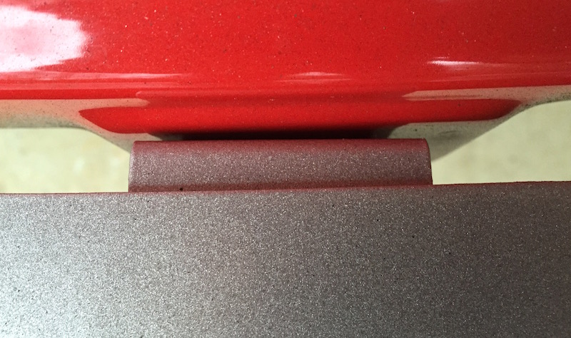
Rear bumper corner edge
This bend (shown above) took some time to get because of the angle of the rear fender. The front bumper does not have this longer lip and it was tricky to line up with the rest of the body. Remember, the bumper is one complete piece that must fit perfectly. The rear bumpers are also mounted on tabs against the body with rubber spacer washers. Here are the mounts:
Rear fender mount
Rear roll pan mount
And finally, this is a picture as seen from below. For reference, the “button” in the middle of the picture through the opening is the trunk release.
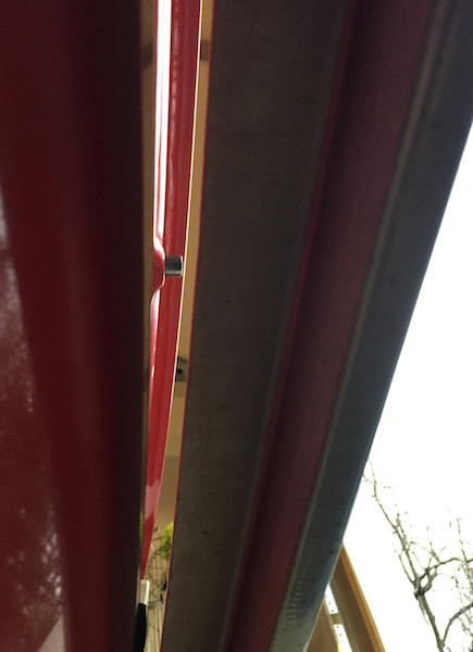
Rear bumper as seen from below
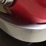
As you can see in the closeups above the powder coated finish turned out very nice indeed. It is as smooth as the rest of the bodywork and gives a very nice, understated look to the bumpers. I did keep a few “imperfections” – I wanted to show these are hand-made bumpers!
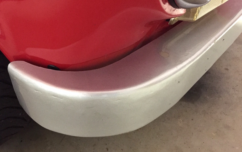
Small imperfections (click on the picture for a closeup)
Excuse the bug marks, stains and overall untidiness… But then again, bowtie6 is not a show car TR6 garage queen – she gets driven very frequently!!
Finally, for a twist on the whole hand made bumper concept, check out the rear bumper on my cousin Jim’s TR4 (click for detail):
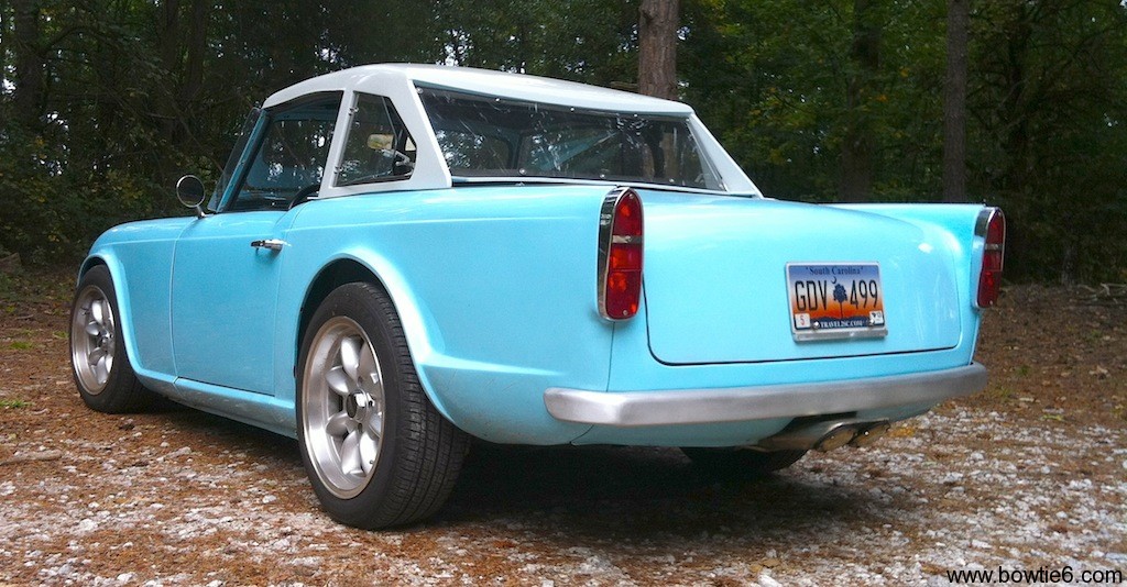
If you are interested, you can read more about it in this article I wrote about an Ecotec Powered Triumph TR4 in this blog.