The Ecotec engine uses a similar fuel delivery system as fitted in the LSx engines in that the fuel rail is “returnless”. This means there is only one line feeding the fuel rail on the engine. In order to make this work, a special fuel regulator with built in filter has to be plumbed not far from the fuel pump. There are several fuel regulator fittings available and in today’s installment I’ll document my experiences.
In an earlier post, I wrote about bowtie6‘s Ecotec fuel system (click here) where I described the separate staging tank holding the fuel pump. About two weeks ago, I noticed the insulation post around the fuel pump’s B+ terminal my cousin Jim had fabricated had deteriorated due to coming in contact with fuel from the tank. In order to solve this problem, I had to take the small tank out which required disconnecting the fuel regulator fittings. After putting all the bits back together I found the fuel regulator fittings were not exactly “clicking” correctly. They held in place but I was not pleased with the fitment so I safety wired them in place as shown in the following picture:

We can all agree this is not exactly the most elegant way to do things. So why the safety wire? Well, turns out on the little plastic tabs that “click” the blue fitting in place are not exactly the best design in the world. Sure, car manufacturers use them all the time and they work flawlessly. However these are aftermarket units made by Russell (a division of Edelbrock) and they are not exactly OEM quality. I found out this by experience and by reading the latest issue of Car & Craft’s engine swaps magazine. So where is the problem?
The following photo shows one of the two pump-side lines going into the regulator. I’ve removed the fitting so you can see the small ring around the metal tube (more on that later)…

The next photo shows the fitting and the small plastic clip that holds all this together:

The small white plastic clip is very cleverly made. There are two sets of barbs on it. The inner pair locks in place around the ring on the metal tube from the picture above this one. That keeps the plastic piece from sliding out. Then the barbs also lock in place on a shoulder inside the fitting. However in order to make this work, the plastic spring loaded affair must be crisp and not in the least deformed. Taking this apart deforms the plastic clip and this prevents a positive lock.


The last two pictures show the white plastic affair locked in place. As mentioned previously, this assembly is then pushed on the tube in the regulator and if all goes well the two barbs on the plastic clip snap on the ring molded on the tube. All this looks good on paper, but I noticed the plastic “clip” had lost some of its “spring” and this all did not really lock in place so well. The kicker is that these fuel lines are holding 50+ psi pump pressure and if they decide to part ways, well… you end up having a real bad day.
Remember that magazine I mentioned above? There was a very good article in that issue about fuel systems and they cautioned on using these fittings. And, they also suggested an alternative. Unfortunately, the alternative is also made by Russell.
I did call the Russell tech line and talked to a rather abrasive dude on the phone about my experiences. Right of the bat, he was not very interested in my findings nor on making things right. Basically he told me to buy the new fittings and took no ownership to the fact this was a bit on the “unsafe” side. I even told him about the article in the magazine, but he dismissed that too. At any rate why argue with someone unwilling to stand by their product so I ordered new fittings. While not exactly “cheap” (they are about $16 each) quite frankly I rather spend the money and have the peace of mind this is not going to come apart and sling fuel all over the place.
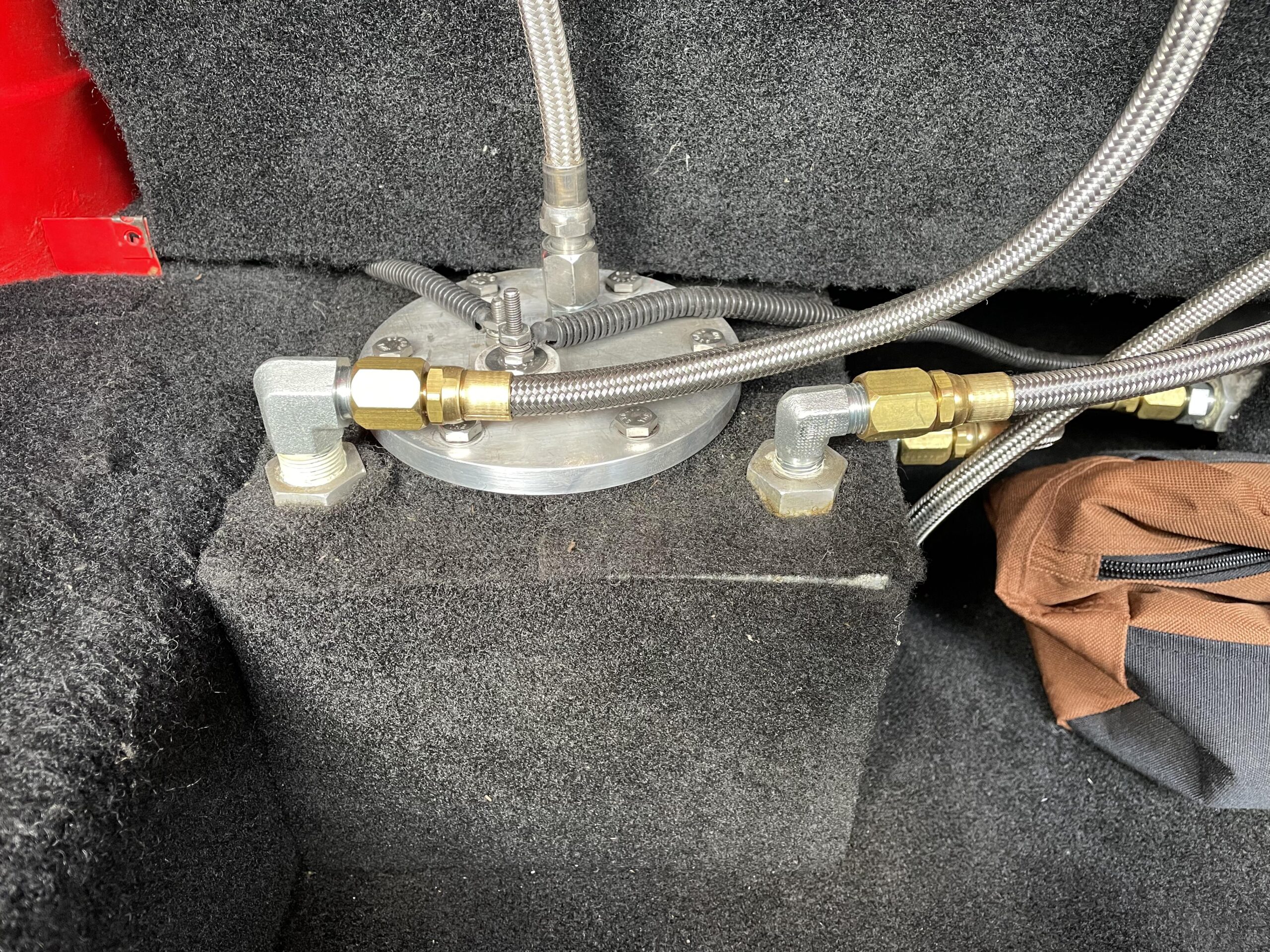
The solution is to use these fittings:

These fittings have a much safer design. Instead of the spring-loaded plastic affair, they have a threaded cap that holds the fitting in place. The threaded cap has a “U” shape that slides over the tube on the regulator and when tightened grips the ring (look at the very first picture on this post) keeping everything securely in place. With this together, there is no slippage and no danger of this ever coming apart.
This is what it looks like all completed:

As you can see, these fuel regulator fittings are much nicer and better designed. If you are considering this for an engine swap, don’t waste your money on the fittings with the plastic spring-loaded clip. Get the ones with the threaded cap. You will be much happier and most important of all, safer.

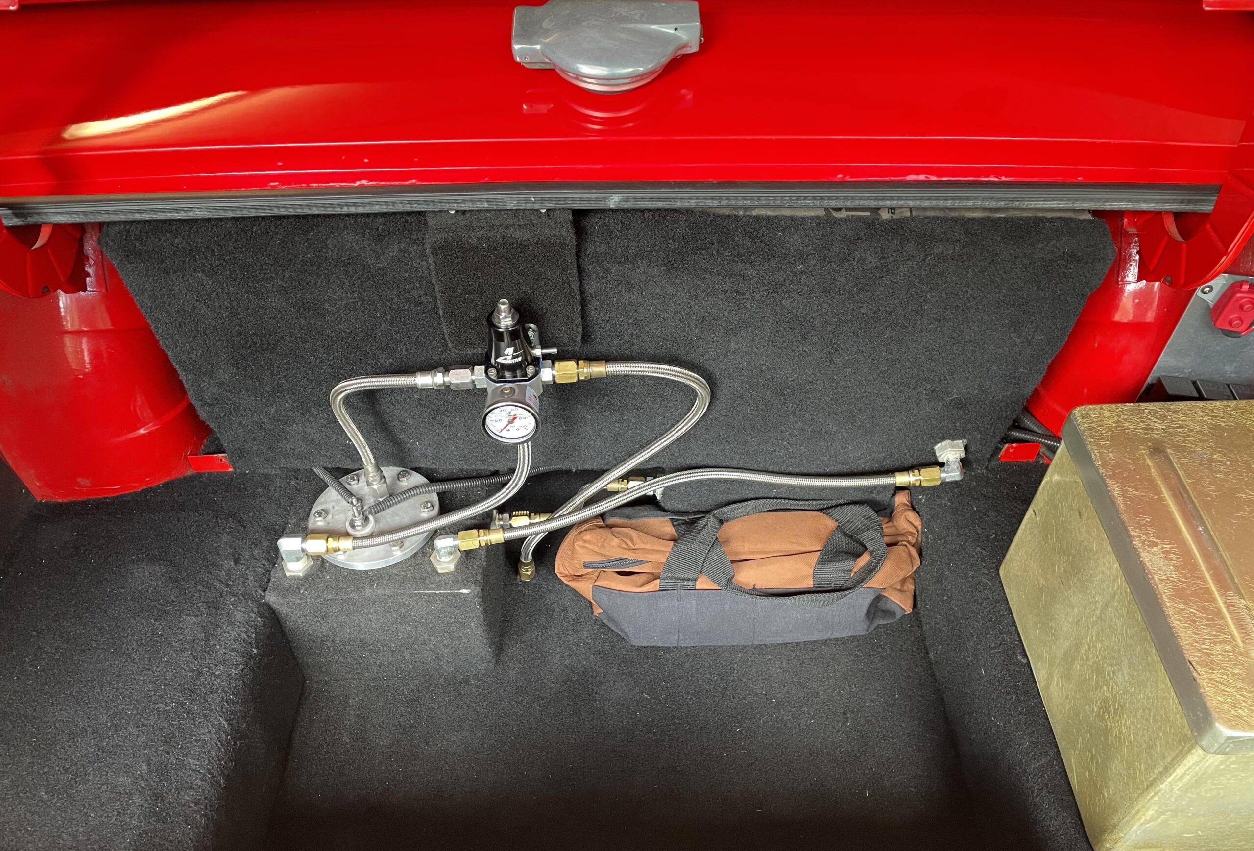 On this 2023 July 4th weekend, bowtie6 got treated to a new fuel pressure regulator and braided lines. The old setup consisted of a GM style non-adjustable pressure regulator and a set of E85 resistant rubber fuel lines – I wrote an article about that (click here). I was never really pleased with the rubber hoses because the braided lines are much nicer and bullet proof. So I pulled the trigger and ordered parts for the new setup.
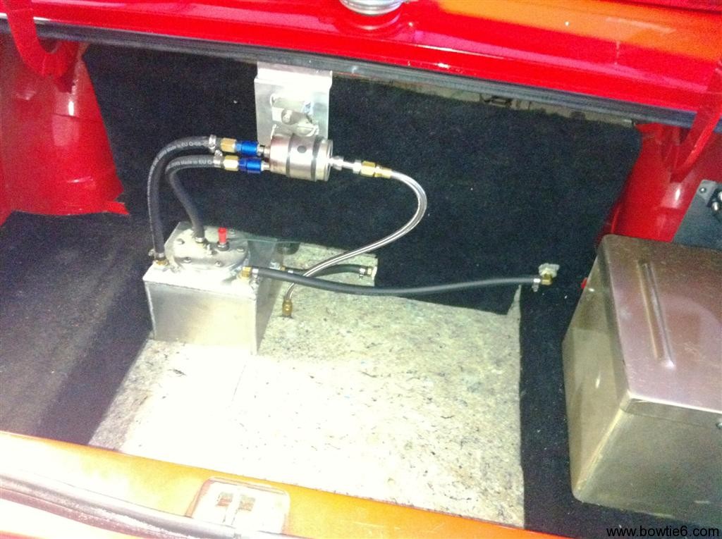
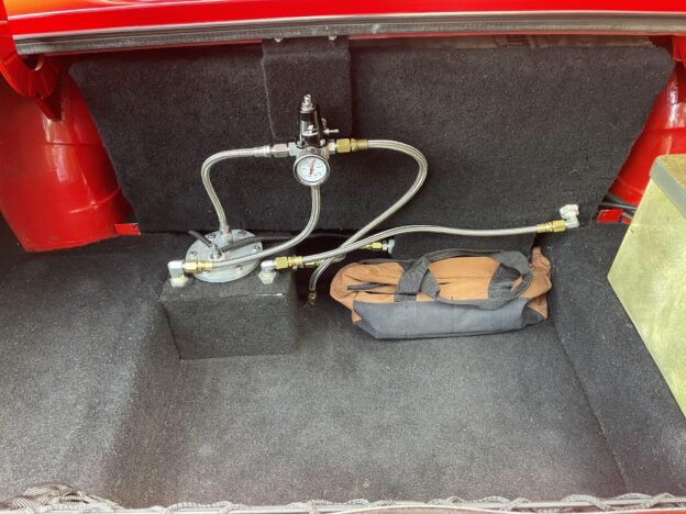
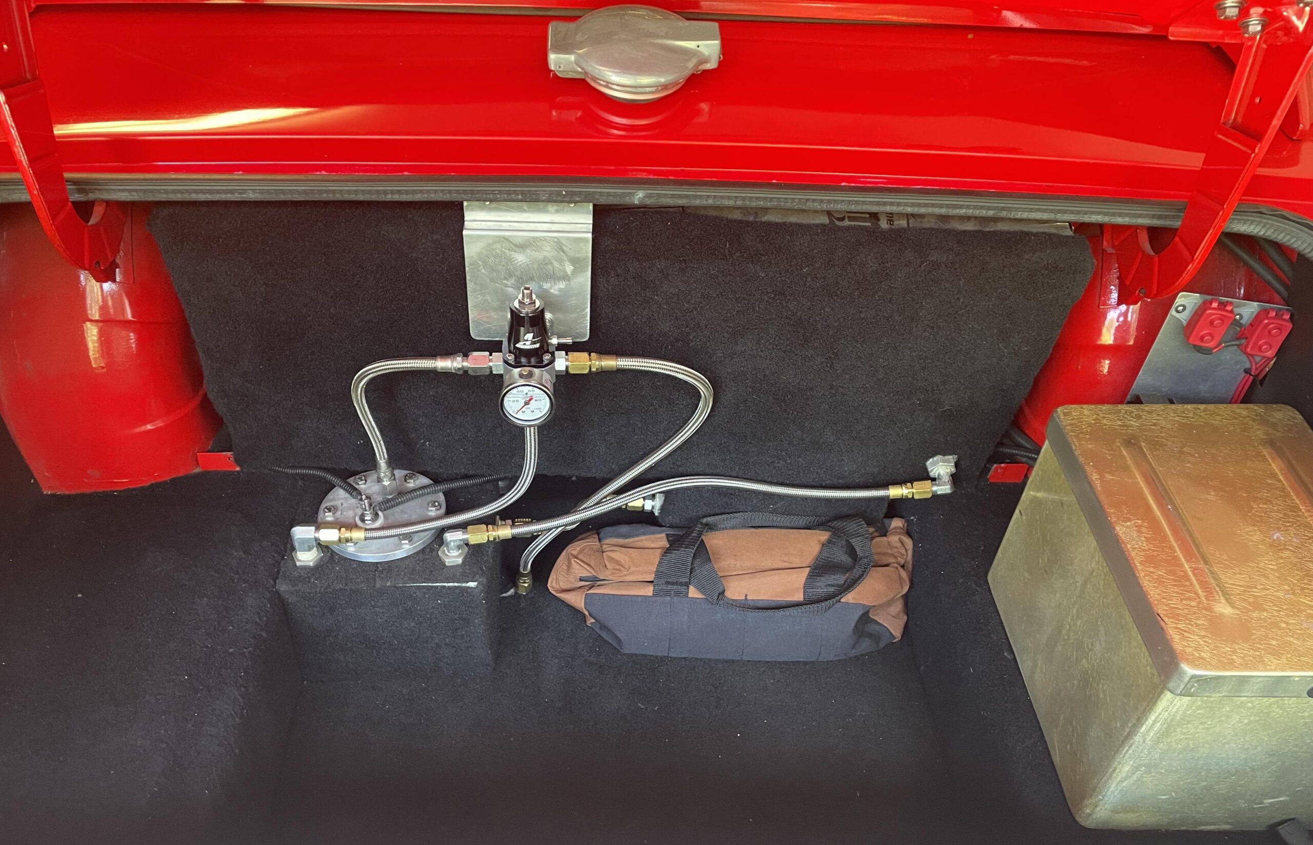 And this is what I mean…
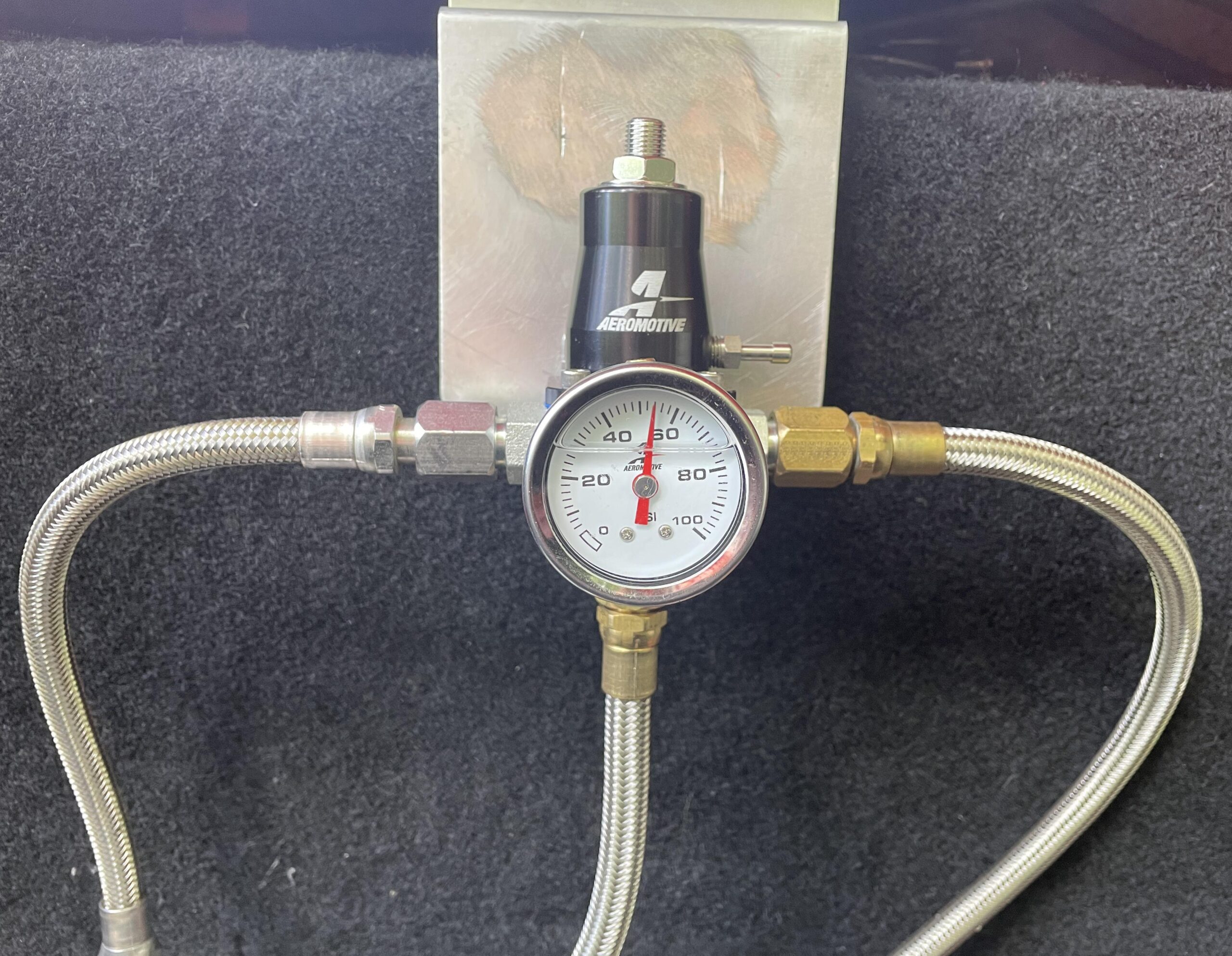 We had to cut the old mount and in the process the aluminum mount got scratched up pretty bad. I tried to sand this down but didn’t make much progress. Instead, why not just use some carpet material?
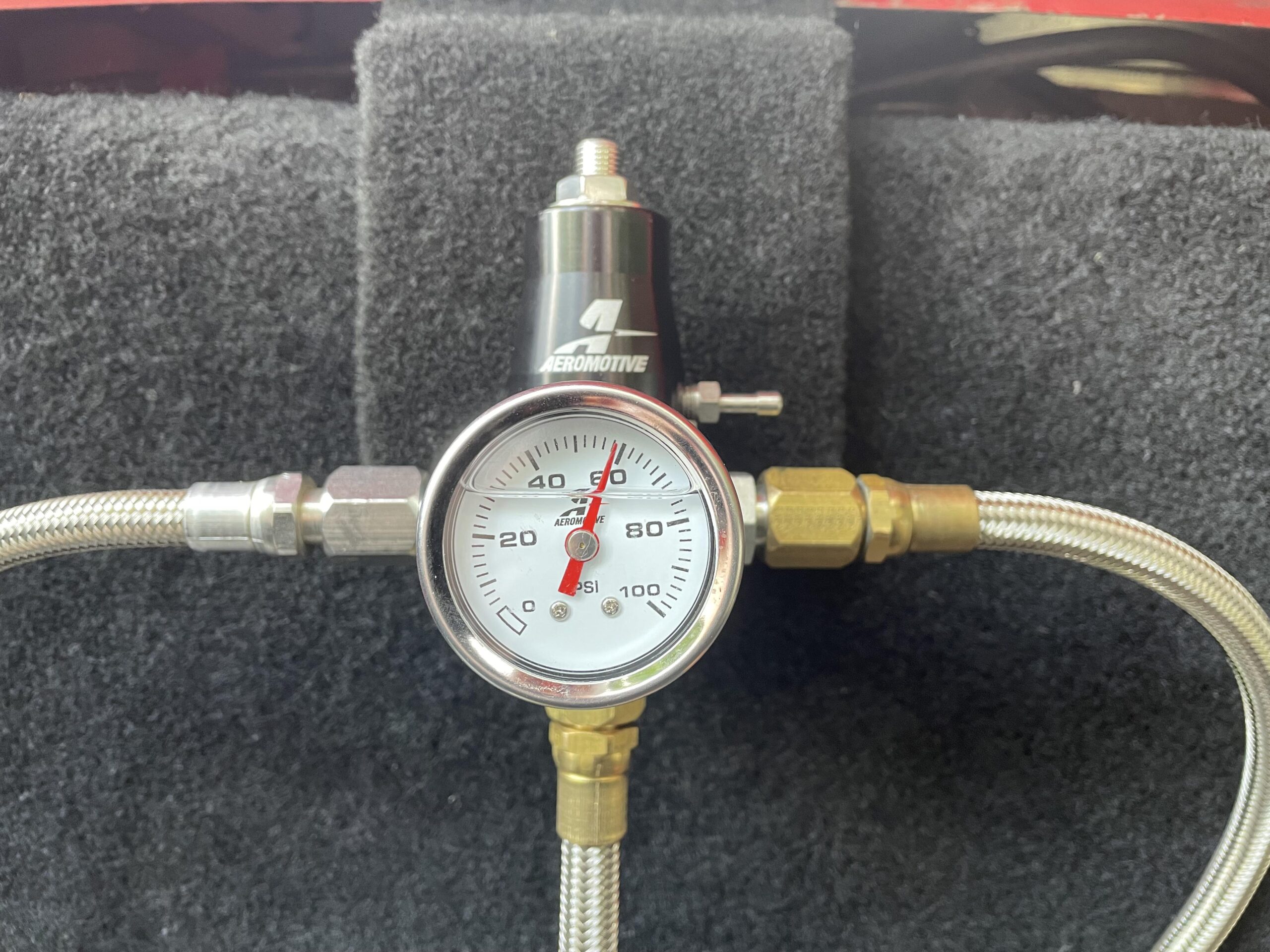 Ah! Much better! A keen eye will also notice the difference in pressure. I checked what the E67 PCM expected, and that was 58 lbs/in, so I bumped that up a bit.
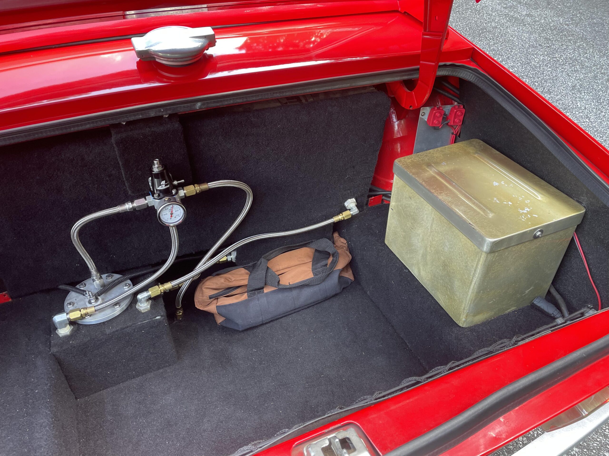
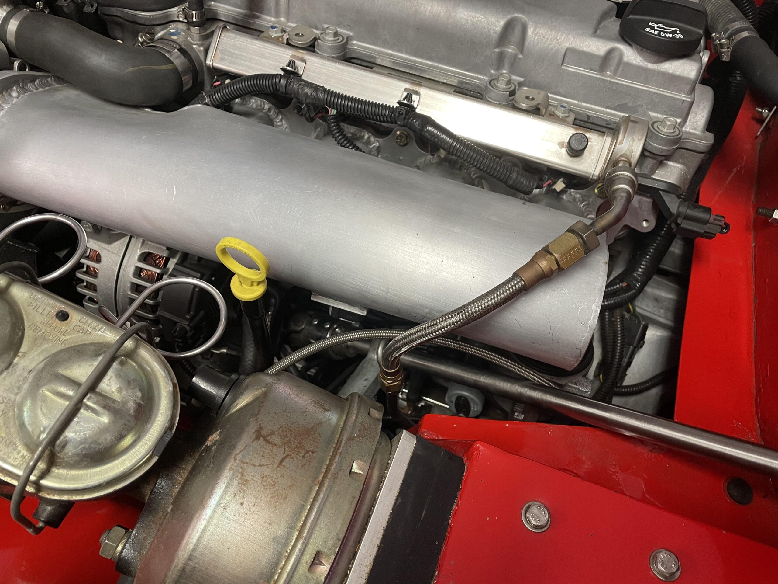
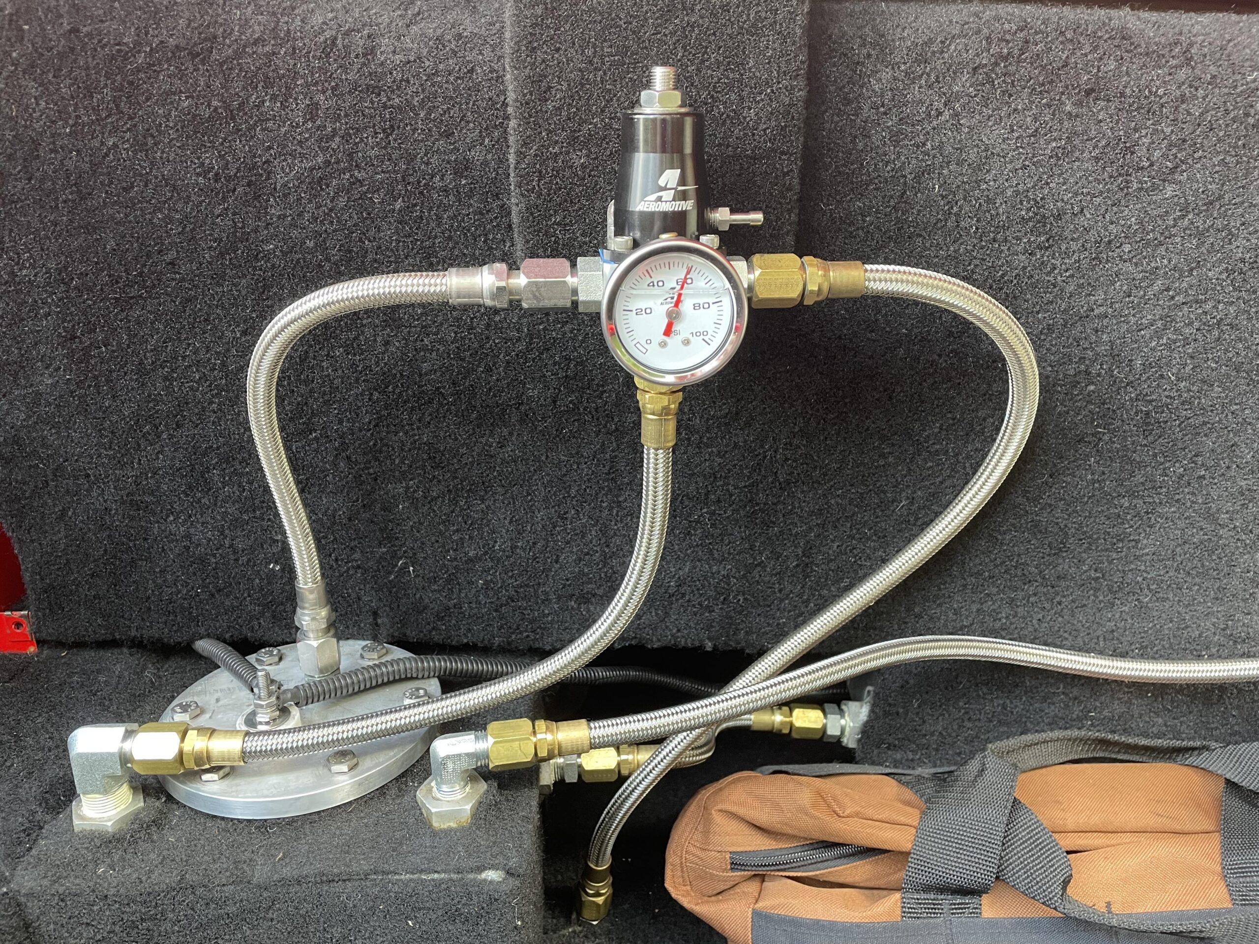 And this is what the front looks like. This is another braided line going into the fuel rail. The other side connects to the stainless tubing under the frame of the car…