
Among the greatest mysteries about Zenith Stromberg carburetors is exactly: “where does the dashpot oil go”? Usually, the reason is a rotten, leaky o-ring in the needle metering screw used to adjust the fuel-air mixture. This article will show you how to replace the o-ring.
Updates:
- Once you read this article, you might want to spend a few minutes reading the article’s comments at the bottom of the page. There are some very interesting remarks there from folks who have contributed their knowledge. If you have any further insight, please make an entry so others might learn.
- If you are interested in getting the replacement O-ring necessary, please don’t forget to read the “Comments” at the end of this article. There is a source listed to where you can find the O-Ring.
Required Tools:
You will need to have several basic tools for this repair:
- A small flat-head screwdriver – to remove the retaining screw.
- A small Phillips screwdriver or better yet, a Pozidriv bit – to remove the four screws holding the diaphragm to the piston body.
- A Zenith Stromberg needle adjustment tool. If you don’t have one, you can get by with a long hex head tool.
- Some spray carburetor cleaner and a few rags or paper towels.
- If you are using a vise, don’t forget to get some soft jaw liners to keep from marring delicate surfaces.
Here is a picture of the tools we will need:

Tools, including a metering needle adjustment tool.
So we don’t get our wires crossed, let me post a schematic of the carburetor. I will try to refer to all the pieces parts by the terms described in the following diagram:

Zenith Stromberg carburetor cutaway diagram.
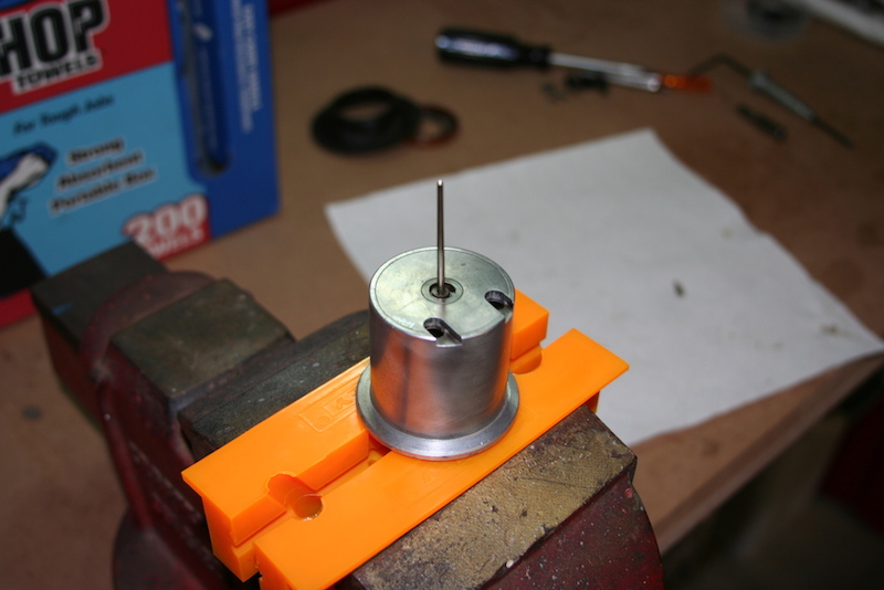
The goal is to remove the needle adjusting screw pictured above. The needle adjusting screw has a rubber o-ring that deteriorates through the years and this is what causes the dashpot oil to disappear.
Before we begin taking things apart, please read this article completely and get familiar with all the parts and all the pictures. If you like, click on a picture for a larger image. This is far from rocket science, just keep in mind the pieces are very small and are easily dropped. So take your time.
Enough talk, let’s get started…
Step 1 – Remove the Retaining Screw
Before attempting to remove the retaining screw, the needle adjusting screw must be backed out all the way out. To do this, introduce the Zenith Stromberg needle adjusting tool (or suitable hex wrench) and make sure the hex head is firmly seated. Now turn counterclockwise a few times.
Now lets work on the retaining screw:

The retaining screw is tiny. It is found on the orifice shown above on the side of the piston.
The retaining screw has to be removed to get the metering needle out. Using a small screwdriver, insert it in the small orifice on the side of the piston. The orifice is on the side of the piston, as shown above. This retaining screw machined from soft brass. If someone has previously attempted to remove this with the wrong screwdriver, it might be damaged. Take care not to make it worse!

Closeup of the metering needle still in the piston.
Before we start taking things apart, please note the small notch on the side of the base of the metering needle. Note that it points in the direction of the orifice (basically it points in the direction of the retaining screw). The screw has a taper and it fits inside that notch. This keeps the metering needle screw from turning and allows it to move up and down.
Even though the diagram above says the retaining screw is spring-loaded, I have yet to see one! All the carburetors I have taken apart have not had the spring. However your carburetor might have the spring, so just be aware of its possible existence. Take the screw all the way out.
Step 2 – Pull the Metering Needle Out
With the retaining screw out of the picture, gently pull the needle out. If it won’t come out, you might have to use the needle adjusting tool and turn it counterclockwise some more. It is possible the threads of the seat are still in contact with the needle adjustment screw. Eventually the needle should come all the way out.
If the needle won’t come out it might be because there is some gummed dashpot oil residue. You might consider using some spray carburetor solvent and let it soak. Remember to use eye protection when you spray that stuff – it is not very eye friendly.
If after all this effort, the needle still refuses to come out, then there might be another thing to consider: the hex shoulders on the needle adjustment screw might be rounded out. This happens a lot from previous owners using the wrong tools or over tightening things. Remember, brass is SOFT! If this is the case, that might be the reason you can’t get your carburetor’s adjusted properly.
At any rate, if you think the hex shoulders are rounded off there is another way to take the needle out and I have that procedure listed in “Step 6” below.
This is what it should look like once the needle is out:

Metering needle, showing the little machined slot where the retaining screw fits into. This keeps the needle from turning when being adjusted.
Step 3 – Remove the Needle Adjusting Screw
The needle adjusting screw is where the o-ring is. This is what we need to fix. Removing this is a little tricky because what holds the needle adjusting screw in place is a little star washer that grips the walls of air guide valve rod. The best way to remove it is by placing a drift or wooden dowel in a vise. Then place the piston on the dowel and very gently tap with a small hammer. Use a small block of wood between the piston and the hammer so you don’t strike metal against metal.
IMPORTANT: Make sure you have the piston in the correct direction. You want to put the side where the needle was against the drift or dowel. You want to tap the piston down, thus forcing the needle adjusting screw upwards so it exits on the top of the piston.
Here is what things should look like once the metering needle screw has been “tapped” out:

Closeup of the star washer with the metering needle adjustment screw below it.
As you can see, the little star washer is almost about to come out. Use care not to drop the thing, they are hard to find on the floor! With another small tap, the star washer and metering screw should come out. The needle adjusting screw should look like this:

The needle adjustment screw. NOTE: the O-ring.
Here it is! You can see the little rubber o-ring on the screw. The top part has the hex shaped recess where the wrench goes in. The bottom is basically the threads that go into the metering needle. This is how it looks like:
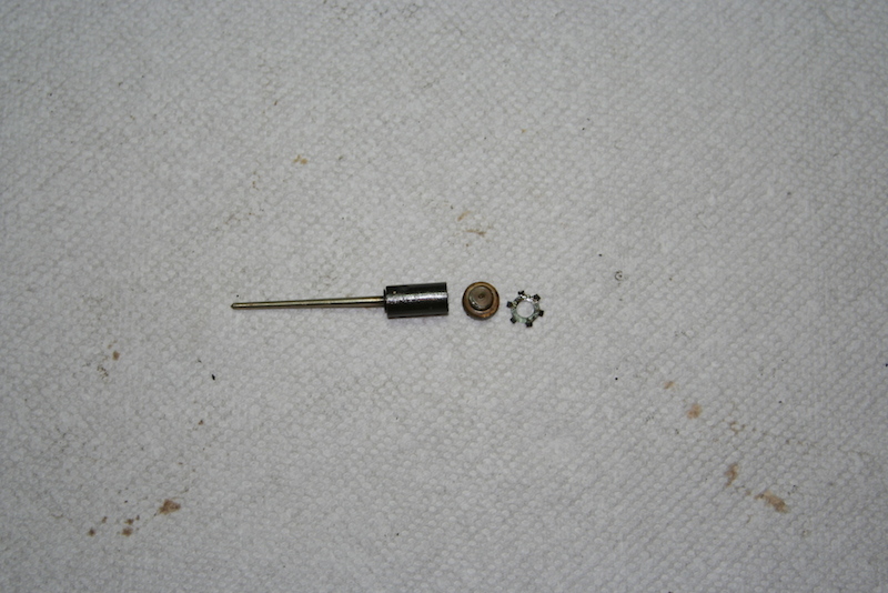
Metering needle assembly; needle on the left, needle adjustment screw in the center and the star washer on the right.
The little star washer and the retaining screw keep the assembly from coming out. Once the nut, washer and metering needle are removed the piston is pretty much hollow inside, as shown in the following picture.

Brass housing for the metering needle
Step 4 – Replacing the O-Ring
As seen in the earlier pictures, the o-ring has flattened and does not fit tight. This one is in decent shape, however I have seen some that literally fall apart when the metering needle screw is taken out. The replacement o-ring should be made of Viton. Viton will hold up better to oil and fuel fumes. Unfortunately, I do not know of a source for an o-ring this small. If you know of one please let me know and I can update this paragraph.
This is also a good time to thoroughly clean the piston and make sure it is free of any carbon buildup. Finally a little Marvel Mystery Oil should be used inside the shaft so the new o-ring can slide easily – no point in messing up the o-ring during assembly after all this effort.
Step 5 – Assembly
Installing the metering needle screw with a new o-ring will take a little patience. Place it at the top of the guide rod and gently push on it. You want to make sure it is level.

Insert the needle adjustment screw like this…
Once you have the needle adjustment screw started, add the star washer:

Star washer in place; note the washer is slightly “cupped”…
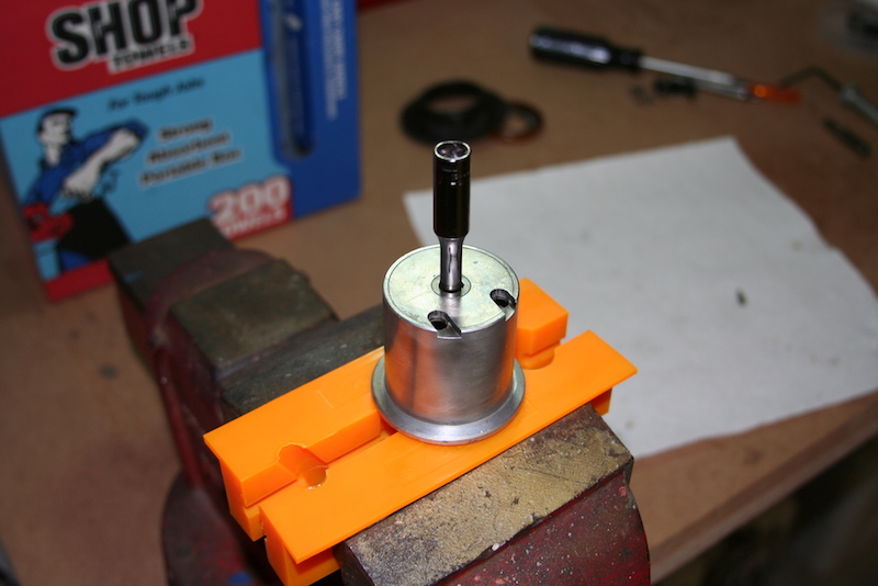
Now use a 5mm deep socket and gently (very gently) tap with a hammer. This should get the needle adjustment screw and star washer traveling in the proper direction.
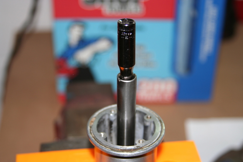
Using a 5mm deep socket to seat the metering needle screw and star washer…
Since the socket will bottom out (it is not long enough) use a drift or dowel to gently drive the components down. A blunt pencil would be a suitable drift. Just tap and eventually you will feel the metering screw bottom out. The last step will be to insert the metering needle back in. Might want to coat the assembly with just a drop of oil so it will slide in easily.
Getting the metering needle re-inserted; note it is not a perfect 90 degree. Instead it has a slight angle – read more about this in the comments section…
Now, get the hex adjusting tool and turn the metering needle screw as you push the needle in. Do this until it catches the threads on the needle. Of course, the needle will want to move around a little and this is where that detent will need to line up perfectly with the hole where the screw goes in. Put the screw back in and tighten it a little. The following picture shows what the screw looks like fully seated:

This is what the screw looks like all the way in without the metering needle.
Now you see why the little notch has to line up in the exact place where the screw is. You should now be able to turn the hex tool and the needle should not turn anymore. At this point you should see the needle start to walk back into the piston. This of course is the way you adjust the mixture in your carburetors.
Step 6 – Alternate Needle Extraction Procedure
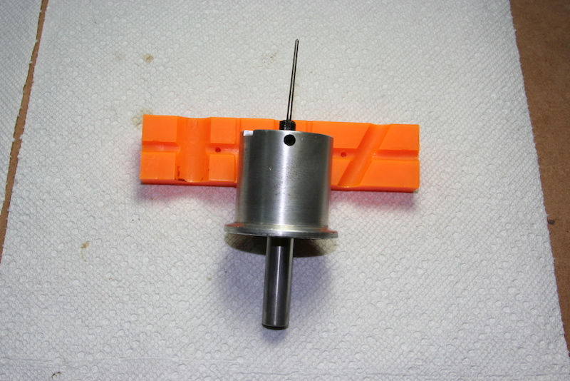
If the needle refuses to come out gently, there is another way to get the needle out. No, it does not mean we get medieval on it! I tried this on a spare carburetor and it worked. The needle can be pushed out from the bottom of the piston and this is done as follows. Mount the piston with the needle facing up like this:
Now, carefully place a 4mm deep socket over the needle like this:
Gently, very gently tap the socket with a hammer. You should see it start to move. Remember you will be tapping against the star washer, so this is going to have a little resistance. As this starts to move down, you will run out of travel on the socket. You will need to insert a slender, longer rod to gently tap the assembly out. Eventually it should come out.
I had to remove the metering needle on this carburetor to take all these pictures. It took a little patience but eventually the needle came out. And, sure enough the hex shoulders had been rounded off. This is what the metering needle nut looked like:

This metering needle screw had the hex shoulders rounded off.
It goes without saying that a metering needle screw with rounded hex shoulders is pretty much toast. This is not going to allow you to adjust the needle. You’ll have to buy a new one.
The “Delrin” Washer
If you read the comments below that other readers have left you will notice there is a discussion about the “Delrin” washer. As best I can tell, this picture shows this “Delrin” washer.

The little round disc is the Delrin washer.
Basically I gently clamped the metering needle in the soft jaws on my vise. Once I had that clamped I tugged on the needle. Since this is a spring-loaded affair, you can see the little black washer comes out with the needle.
Diaphragm Alignment
I have been asked how to align the rubber diaphragm. Well, there are a couple of alignment tabs on the diaphragm that must align with a matching grove. This is what the alignment tab and groove look like on the carburetor bowl:

Alignment tab and groove on the carburetor bowl.
Look on the right edge on the carburetor bowl. There is a small groove. Now look on the diaphragm, there is a matching tab. Of course, the diaphragm is upside down here – I did that to show the tab.
The piston has an alignment tab and groove too. They look like this:

Alignment tab and groove, this time on the piston.
You can see the piston has a groove (to the right of the two screw holes). The inside rim of the diaphragm has the matching tab. Again, the diaphragm is upside down. If you line all these indents the diaphragm will be correctly seated and should seal properly.
You must align everything up before you securely screw the rubber diaphragm to the piston.
About the Phillips Screws…
For some strange reason I have yet to figure out, the Brits made things complicated when it came to fasteners (after all, we have to thank them for Whitworth). I don’t know if you have ever noticed that a Phillips head screwdriver doesn’t fit right on the Phillips head screws on the carburetors. Well… That is because those screws need a special bit.

Pozidriv size #2 bit
Do yourself a favor: go to your local hardware store, auto store, Sears, or whatever you have near and get a set of special Pozidriv bits for these screws. I picked up a handy three-pack which includes the #2 bit as well as the smaller one and larger one. These will fit the Phillips screws perfectly and you won’t be rounding off those heads. They also work perfectly on the four screws that hold the carburetor lids in place. They can be really handy and no toolbox should be without them.
Conclusion
I hope all these pictures and my explanations are of some help to you. I don’t claim to be an expert in Zenith Stromberg carburetors (not even close!) – in fact I really dislike them. This is the reason I like fuel injections so much. However these were tricks I learned when I owned a Spitfire. I hope you find this article of interest and it can help you solve your dashpot oil consumption problem.
Comments are Very Welcome!
As always, any suggestions, clarifications or questions are very welcome. Like I said before, I am no Zenith Stromberg expert. However, this page has been read by many, many folks and if you have any other info that might come in handy for anyone with these relics of automotive engineering then please let me know. That is what the comments section below are for.
I have replaced the o-rings twice now, one still leaks badly. Its as if the surface the o-ring is sealing against has worn or pitted not allowing the o-ring to seat correctly. Not sure how i could make he surface smooth again to allow the o-ring to seal properly.
What kind of o-rings are you using? You must use Viton as that withstands oil and fuel vapors the best. If you use just generic rubber o-rings, they may be deteriorating and not providing the proper seal. Other than this, I have no other ideas – I wrote this article as a guide to what could possibly cause damper oil issues; since I don’t run ZS’s on my TR6, I am afraid I cannot help you more. Sorry!
Thanks
Thanks for the very informative article. It has greatly helped me to get the needle and adjusting nut out. they have got gummed up in car that hasn’t run for decades.
I wish to thank those who posted their problems. these have shed light on unique problem solving methods.
Hello!
The pistons on my CD 175’s are older models which don’t have the slot to use the “tool” to adjust the needles from the top. Mine are “fixed needles”. So to adjust them, I must remove the entire piston and re-installing them until I’m happy with the setting. Here’s my question: can I replace these fixed-needle pistons with adjustable ones? If so, where can I buy the new pistons? If unavailable, can I just buy used carbs (for parts) somewhere that have the adjustable pistons and install them into my existing CD’s? Thank you!!
I have no idea if the pistons are interchangeable. This is probably a question best suited for one of the variety of LBC forums out there. I am sure somebody can guide you better in the direction of who might have an answer for this.
I can see that not having the ability to adjust the needles would be a major pain – i’ve never heard of this though, so this is news for me.
Sorry I can’t help you…
Thanks, Joe.
I’ll get there in the end … hopefully.
Chris
i have tried many times to adjust/synchronize the dual 175 on my TR 250, which currently has CD2/3?( air piston tube has two notches to hold allen wrench carrier)
problem is after taking air piston out and in, cannot get cars to adjust and be synchronized (when carbs are not together in linkage, and air flow meter is put on air piston intake throat) the engine dies (both carbs act the same when meter is put on carb intake and cut off)?
any ideas
i really found the article most informative
my base washer on needle is initially positioned at 2mm counter sunk into piston damper tube, before allen wrench adjustment
Tony
I hear you. And the exact description you are giving about those carbs is why I am running a modern engine with fuel injection. Hold long ago since you had your carbs professionally serviced? Sorry, I can’t help you on that. Perhaps you might want to post your question over at the TR6 Six Pack forum – there are a lot of very good folks there that still mess with these carbs.
Hello, Joe.
I would have dearly loved a TR6, but missed out and ended up with a TR7. Big mistake !
Anyway, in my search for guidance on the Stromberg 175 CD, I have found your site to be one of the most informative.
However, the carb fitted to the Mercedes W123 that I inherited from my father is a CDTU. It doesn’t have the two ‘notches’ at the top of the air valve guide rod, and adjustment appears to be by way of a recessed nut at the exterior bottom of the float bowl.
The car was given to a Mercedes ‘specialist’ garage … and they succeeded in messing up all the settings when the problem was simply a slight tear in the diaphragm !
Would you happen to know of any other sites like yours that I might look at to find a solution for correctly adjusting mixture ?
Thanks in anticipation.
Chris
Sorry Chris – I do not. Those carbs are so old and the amount of folks that really know them is becoming smaller and smaller. Not surprised your “specialist” garage had no clue. Hell, finding a good mechanic for modern stuff is hard enough.
Carbs are not my thing; I wish I had more info for you but this time I am all out.
Thanks for the great site, John. I followed your instructions and had a perfect outcome. The O-rings are 1/4 ID by 3/8 OD. I bought mine at Ace Hardware for .69. Ace’s website claims they are made of Nitrile, which Wikipedia says is fuel and oil-resistant.. I’m keeping a detailed journal on the restoration of my ’73 TR6, and, with your permission, would like to print some of your photos and instructions in it (with attribution, of course). Would that be acceptable to you?
Tom Landry
Thanks Tom – sounds good to me. Just make note, my name is Joe, not John.
I’m glad you found the article about the ZS’s of help.
If you have a website let me know the URL and I’ll be happy to link it here.
Cheers!
I know this article is oldish but I will try anyway. My 175 CD carburetors do not have the star washer shown. I have a slot in the top of the piston where the adjusting tool goes so I assume it is adjustable. But nothing seems to adjust..
“Oldish”… LOL! As if the subject matter (the ZS carbs) was bleeding edge – go figure.
The star washer is what holds down the metering valve screw from backing out completely – no wonder nothing “seems to adjust”. If the star washer is missing, I would check to make sure the metering valve screw still exists. If that is gone too (likely, since no star washer is present) then you have bigger problems. That means the metering valve cannot be adjusted and you will play hell trying to get that carb to play nice.
Good luck!
Just wanted to add to your excellent guide.
Mine are a pair 175 CD-2 from a Lotus Elan and despite an excellent supplier here in the UK. Burlen, diagrams are in short supply.
The kits provided for my carbs. include new jets, new spindle and butterfly, new seals and of course new diaphrams and gaskets. As one of your earlier contributors stated there are lobes on either side of the diaphram ensuring the needle is correctly aligned with the jet.
My carbs have a fixed main jet which is a press fit and adjusted to sit 100 thou./ 2.54 mm below the bar across the throat. The needles then drop in to these jets and can be adjusted as you state by turning the nut inside the diaphram tube.
Your diagram was essential in showing and describing how to remove the screw that holds the needle. Really useful to see how it’s assembled before using a hammer, however small, to remove it.
It’s worth noting that I needed to specifically ask for new o- rings for this screw which ought in my opinion be supplied with the new needles. Please note the needles were in addition to the overhaul kit.
For other users it’s also worth noting that the float height is difficult to adjust. Physically it’s straightforward but they lie at an angle making it difficult to know from where to take the specific measurement. I suspect this is fairly critical to the mixture since it effectively varies the height of the fuel supplied to the jet and would therefore deliver differing amounts for a given drop in pressure.
Once again thanks.
Thank you for your detailed comment Mark. I appreciate it. I am glad you were able to find this article of good use for your Lotus.
“Simplify and add lightness”, right?
Cheers!
I’m a new owner of a 1975 MGB with carb issues. My piston has a stripped set screw(the head) along with the head of the metering needle being stripped. Any ideas how to get either of them out? Please email me at hyveematy@gmail.com if you receive this. Many thanks!
Hi Matt:
Have you tried to contact the major parts houses to see if they might have the replacements you need?
This is absolutely the most comprehensive explanation on how the needle is affixed and removed. Great pictures and text. Thank you…..
Glad you have found value in this article. Stay safe!
Carlaw Carburetor. Queen St. East and Carlaw. Entrance around the back.
Thank you for the information!
i thank you very much for sharing your knowledge in this field though you said you are not expert, i was impressed by the information you had shared. i learned a lot after reading it. as you said ‘patience’ so i patiently read everything ’cause i have an MG MIDGET 1977 that had been seating in my garage for 30 yrs. , and i finally made run but idle is very rough that i can not drive. where can i buy this metering needle adjusting screw O-RING ? i checked Victoria BRITISH and MOSS parts stores but they dont have it. thanks again.
Thank you for your comment. Unfortunately I have no idea where to get the O-rings. Perhaps you could visit a local industrial hydraulic supply store and they might be able to help.
I bought a Moss CD 150 rebuild kit and it had the O ring. Tom
I had the Stromberg 175’s professionally rebuilt last year by a good carb guy here in Toronto. The car starts well with the choke on and runs smoothly. However, after backing off the choke, it will not hold an idle and will stall. I was wondering if it was a full mixture issue but after reviewing the above article, I’d rather not have to mess with the adjustment if not necessary. It is still rather cool here these days; 6 Celsius, 42 F and the dash pot oil slows the piston movement down considerable; heavy upward movement and no pronounced ‘click’ when the pistons are dropped, and so I’m wondering if its simply a cold engine issue.
Any thoughts would be appreciated. Thanks.
BC
Sorry but I can’t be of help. I no longer run Zeniths on my TR6. Perhaps someone reading this might have some insight into this.
A Stromberg re builder in Toronto? I’m working on a ’76 TR6 with dual 175’s on it. Who is it that rebuilt your carbs? I’d like to give them some business!
sounds like the float needle valve is stuck open or the floats itself has sprung a leak and is full of fuel and won’t float ( if it is the hollow kind. )Will the needle in the piston adjust down almost flush?. also the jet itself may be worn oblong and the needle will never shut down the flow enough. also make sure the float chamber vent is open.
1980 MGB with the Zenith 175 carb. I have had this carb apart 5 times. Pressurize the float chamber with the fuel pump. No problems. Put carb on intake and try to start and the fuel keeps flowing through the carb. Do not know if the O ring and Delrin washer are suppose to prevent this.
Thank you for your post. Unfortunately, I have no clue how to fix your issue. Might want to check on the model-specific forums where folks with more experience with ZS’s might be able to help…
I had a similar issue. It was the float chamber needle valve to closing properly due to dirt in the top. Bought a new valve and fixed the issue. Also check that the floats are set at the correct height as per manual for your car as manifold angles will cause variations. This helps ensure fuel flow and cut off happens correctly.
Sounds like your float is not adjusted, and it will let fuel “freely” flow into carb and flood everything! Take it from me!
Thanks for your post. I just stumbled on this post after I just finished removing and reinstalling the valve needle. Had I seen this earlier, I would have replaced the o-ring while everything was apart. I guess this is a project for another day.
I have a stock 79 mgb with a single 175 CD5T Zenith Stromberg with manual choke. The automatic choke and some pollution parts were removed by previous owner, such as air pump, air pump cleaner and check valve. The gulp valve is in place but not plugged. I can’t seem to lean out the carb. It runs so rich that my clothes become saturated with the smell of exhaust/fuel when the car is running even for even the shortest time. My plugs are sooty and it spits black soot out the tail pipe onto the garage floor. I don’t see any smoke from the tail pipe.
I’ve tried using the special carb tool and turned the idle screws counter clockwise but nothing seems to help.
Any suggestions on how to get rid of the stinky exhaust smell would be greatly appreciated!
Thank you in advance for your time.
John
Thank you for your post – unfortunately I am unable to offer any suggestions on your rich running carb. I posted this article to show what the guts look like – I do not have ZS’s on my TR6 exactly for this reason!
I worked on nearly the exact same car/carb setup (except for automatic choke) for a couple years trying to get it right. But the problem it had was too lean and I diagnosed vacuum leak early on. However, there were many leaks and of course I didn’t find the main one until I had fixed all the others, it turned out to be two access panels directly under the manifold on the driver’s side of the engine, bolts had come loose and gaskets were bad.
Having said that, I did run across a slightly rich problem while working on it, a buddy had replaced the fuel pump earlier and it had too much pressure. Those cars should only be running 4-6 PSI max (4 is better). That ZS 175 sips fuel using vacuum only, and if the needle valve on the float isn’t adjusted just right, a strong aftermarket pump can flood the carb. And that is the only thing I can think of that could possibly cause it. If you haven’t rebuilt the carb already, I recommend you do so, and I recommend you also replace that o-ring. If it’s not holding oil, then it’s a source of vacuum leakage, and that carb is very sensitive to vacuum.
heavier oil in th damper may help lean out ur mix , and this sounds like what u need, also the float level is important (check ur manual) make sure the needle lever is square to the needle , if it isnt it closes the needle off center and can allow more fuel into the chamber after the floats should have shut it off. failing all this ur metering needle and its seat may need replacing,
good luck.
It is possible to detach the needle valve from the adjustment screw by mistake by turning the adjustment screw counter clockwise too much, which obviously would keep you from being able to adjust the mixture. Pull the piston out of the carb and observe the needle while turning the adjustment screw. If the needle valve does not move, the screw has been turned counter clockwise too much, un-screwing it from the needle valve. put some light force on the screw with the allen wrench and turn clockwise while lightly pushing the needle valve up into its bore. Once the screw and the needle valve are re-threaded you should be able to adjust the mixture. Just be careful not to un-screw the adjustment screw too much!
I had a similar problem – I found out I had turned the carb adjustment tool screw too far counter clockwise which made the adjusting screw come loose and it wouldn’t adjust the needle any more until I got it screwed back in turning the adjustment tool clockwise.
Quiero dejar mi agradecimiento y felicitaciones ya que es para destacar que alguien se tome el tiempo de mostrar con tanta claridad y conocimiento lo que puede ser de utilidad para muchos otros y en forma gratuita.
Su explicación me ha sido de mucha utilidad para comenzar a restaurar por completo mi juego de twin strombergs 175 cd 2.
Nuevamente gracias y felicitaciones.
Fernando – Buenos Aires / Argentina
Muchas gracias por el saludo y el comentario – me da mucho gusto saber que el articulo le sea de buen uso.
There is a small hole partially covered by a bent brass plate on the right hand side of the carb looking towards the manifold. What is this? I think that my float valve is not shutting off properly, and when I primed the fuel pump, petrol came out of this hole.
The car has not been run for around 8 years, and much of the work I did during the restoration now needs to be done again. Stuck clutch slave, dry seals etc. I wonder if this is just another one of those lack-of-use problems.
Thank you for your question, John. Unfortunately, I have no idea what the purpose of the area you describe. Perhaps someone reading this might be able to resolve this question. Thanks again for your visit!
yes it is lack-of-use problem. my mg midget 1977 was in the garage for 30 yrs. , and i tell you i did a lot of work on it, its a nightmare but finally its running but a very rough idle.one thing that i found out when it smoking too much is when you put too much oil in the air valve\ damper assembly.
Hi,
Thanks for a nice page.
We just got a -71 TR6 with Stromberg CD2 carburettor.
It was no oil in the Oilcamber, so we filled it up, and tried to start the engin. The air filters was not on.
When the engine started the gas was “spitting” out of the went port at the air filter assembly side, (only in one of the carburetors). The engine was running very quickly. We stopped the engine.
Was the gas flow caused by broken diaphragm?
To little oil in the camber?
Any other reason?
Best regards
Aage,
You might want to take a look at the Grose jets. These are small check valves located in each of the fuel bowls below each carburetor. You will need to take them completely off the intake manifold and place them on a workbench to properly disassemble them. I am no expert in these relics so I really can’t help you more – I sure wish I could…
Good luck and please, post a comment once you get the problem fixed – this way others might be able to learn from you.
Cheers!
Hi again,
Thanks a lot. We’ll have a look, and give you feedback.
ÅgeB
This is an excellent post and helped me refurb my Stromberg CD 175 on my Volvo 240. However Volvo seem to use a different tool to the standard Hex one , so I hit a few problems , also the manifold to carb gasket from Burlen supplied in the kit is incorrect and the car won’t idle currently. However this is fixable! Again many thanks for this excellent article.
Thank you Geoff. I appreciate your positive comments! Good to know this has helped.
The stromberg carbs on my Datsun 240Z don’t seem to have a mix adjustment anywhere under the base. Other SU’s (Mikuni?) stock on 240Z’s have a very simple adjusentment under the base. My question is…where is the adjustment located. These have a 90* angle at the top of the round dash pot…?
Thank you for your comment but I have no clue about your Strombergs. I sure wish I had a 240Z though! Perhaps a visit to a Datsun-Z forum might help? Good luck!
On the later stromberg the mixture is adjusted by using a special tool. The tool is inserted after remiving the oil cap / damper and when turned moves the needle up or down in the piston assembly. There are two types of tool one is allen key type the other is a forked type. Try a range rover forum as thes were fitted to models in the 80s
Thank you for you clarification, George. Much appreciated.
Very nice write up! Thanks.
The early ZS had the press to adjust jets, fixed needles. You can fit later pistons with adjustment to these early carbs. We use to just tap the jets up or down with a brass drift. PITA though!
I worked at a TR dealer c 1964 – the first ZS sighting on the TR4 – they were so bad the factory sent us SU on manifolds, told us to throw the ZS setups in the trash, complete.
I always found the O ring in the repair kits, but it is so small it often hides in odd corners of the bag or vanishes completely! Before I knew what it was for, I accumulated many, which of course I have since lost.
I think the Delrin washer is only on some, certainly not all. It would be related to the needle holder assembly era.
PoziDrive is a US patent, same owners as Phillips. What is weird is that the US makers did not adopt it as standard. It was invented to take more torque for power driven screws, and it does that very well.
FRM
Fletcher –
Thank you for your comments. I have edited your prior post and removed the comments about vendors/repairs – sorry but I don’t endorse any of the vendors you mentioned. Very informative about all the other info! Thank you!
Thank you for putting this on YouTube I found it very helpfufl as I have a humber scepter Mk.3 with Stromberg carbs. Thanks to people like you it helps people like me repair our vehicles.
Thank you for your kind words.
However, I don’t recall putting this on YouTube – please, post back the link you found on YouTube about my Repair Guide.
thanks!
Sorry I just put oil leaking on Google and thought it was u tube.not very good with this tecknolegy. Thanks for your help any way.robert paul.
No problem! Thanks!
Thanks for the info
This post was very helpful and clear. Thanks for the write-up.
Thanks for the feedback – I’m glad it helped.
I struggled all winter to tune a 175CD ZS carb after rebuilding it (thanks to this blog for telling me how to replace the dashpot oil seal) in a ’79 MGB. Had all the symptoms of a vacuum leak but could not find it, until I started checking out the 4th gear vacuum advance vacuum relay (all lines and the relay itself checked out good, as did the 4th gear switch on the gear shifter), and found that the relay has a port opening on the underside (invisible and unknown to me until I pulled the relay and tested its operation) that is open to the atmosphere and connected to one of the vacuum port nipples when the relay is deactivated (but closed off when the relay is activated), and that vacuum port nipple was hooked up to the intake manifold (I suppose because that vacuum port nipple pointed in the direction of the carb & intake from where the unit is mounted near the firewall on top of the fender in front of the driver, whilst the other port inexplicably pointed straight up). Anyhow, this port opening was clearly meant to serve as a bleed-off to the distributor vacuum advance so that the vacuum condition was eliminated as soon as the gear shifter was taken out of 4th gear. So, it was hooked up backwards, and until it hit 4th gear, the vacuum line was sucking atmospheric air (once activated, the vacuum was switched directly to the distributor and the bleed port was closed off). Swapped the vacuum lines at the relay and problem solved. Those Brits, could have made it so that each port nipple pointed toward its connection. Must be a re-purposed part.
However, solving the vacuum leak didn’t solve the tuning problem. I started out with the bottom of the metering needle flange flush with the bottom of the air piston, and the coarse and fine air mixture adjustments (the fine adjustment was a small slotted screw in the middle of the coarse adjustment hex ‘nut’, which is really just a hard plastic housing with a hex head) in the exact middle of their ranges, according to the Haynes manual (I think the coarse was two full turns from bottom-out, while the fine was 2-1/2 turns from bottom-out, or something like that). It was lean starting out (occasional backfire, hesitation accelerating, RPMs dropping drastically when air piston is slightly raised at idle), so I increased the fuel mixture (clockwise 1/4 turn each time on the metering needle adjustment) and quickly encountered a too-rich condition (it wouldn’t restart after full warm-up and driving, unless the air piston was propped up to increase the amount of air entering the carb and enable a restart). There was no in-between, it was either too lean or too rich.
It was then that I realized what the coarse and fine air mixture adjustments were for, and so I started over, reset the metering needle and this time as I raised the metering needle to enrich the mixture, I gave the coarse air mixture adjustment ‘nut’ a corresponding CCW 1/4 turn to match the metering needle’s 1/4 turn CW. So, as I was adding fuel, I also added air. This turned out to be a good ratio of turns, as I reached a point where all lean symptoms disappeared except for the hesitation accelerating, then I reduced the amount of fuel and air enrichment increases to 1/8 turn each until the hesitation disappeared and it ran excellent and restarted perfectly.
The Haynes manual said nothing about increasing fuel and air at the same time. It only calls for adjustments to affect the exhaust sensor readings and not in any particular order let alone simultaneously, and I obviously had no sensor. Definitely not written for the layman. Anyhow, if anyone has a more precise method of doing this without an exhuast analyzer, I would appreciate knowing it. Thanks!
Thanks for this article, I’ve owned and worked on my GT6 for over 25 years but had a problem that I was struggling to find a solution to, that was that the adjusting screw hex socket had rounded off. I was trying to figure out how on earth to change the screw if I couldn’t get it unscrewed to release the jet then I stumbled upon your article and the alternative method of removing the needle assembly was just what was needed. I’ve not found anywhere else where this method is explained so I’m very grateful, adjustment screw is now replaced and I’m able to tune my carbs again 🙂
FANTASTIC!!!!
I’m glad my “alternative” method works. You have confirmed so. Thank you.
Well – this is very satisfying. I really appreciate your kind word. For all the folks that might find this method “questionable”, here is proof it works.
Cheers!
Thanks for responding and for your thoughts and ideas.
John
Sure thing! When you get the needle sorted out, please post back and tell us how it went.
Cheers!
I just finished rebuilding the Stromberg on my 79 Spitfire. The article
was a tremendious help to me. Two comments. the screw that holds the
needle in does have a spring build into the point. Second point. To
remove the complete needle assembly, I cut a piece of steel brake line
about 5 inches long and placed the rolled end of the line over the
needle and gently drove the the complete assembly out. Worked great so
I will try to remember that trick next time. Thanks for all of the
great info. I had not worked on a side draft since my MGA purchased in
1960 so all the information was very usefull. I now have it in a note
book.
Thank you for the kind words. Also, thanks for the tips about the spring and using steel brake line.
Felicitaciones por su escritura en español, bueno te comento que vivo en Lima, aquí la altitud varia mucho en minutos y pocas horas de viaje, la playa esta a unos 30 minutos de mi casa (si es que no hay trafico vehicular) yo vivo en Santa Anita – Lima-Peru, a 195 m.s.n.m , a esa altura, he reglado la carburación de acuerdo al manual es decir primero cerré por completo el perno de ingreso de aire a fondo y luego le di 4 vueltas, después coloque la mariposa de aceleración a 1200 RPM y luego ajuste el ralenti con el mismo perno dejándolo en 950 rpm. con este ajuste viajo sin problemas de la Ciudad de Lima (no toqué el perno de riqueza ubicado cerca al compensador de temperatura).
Pero cuando viajo al este de LIMA (sierra) si tengo problemas a partir de los 1500 metros de altura, una vez viajé a MATUCANA que se encuentra a una distancia de 60 km desde mi casa (195 m.s.n.m), un promedio de 1 hora de viaje por la carretera central, la potencia del auto bajo un 30% aprox. el auto en mínimo se apagaba y debía de mantenerlo acelerado, que tonto que fui pues desconocía que debía de aumentar el ingreso de aire, aun así mi vieja maquina logró su cometido y llegó a los 2378 m.s.n.m. en MATUCANA pasamos un bonito día con mi familia y la tarde retornamos a casa sin problemas. Recién entendí el porque de los turbo alimentadores. en los camiones de carga.
He brindado mantenimiento a mi carburador pero no al 100%, pues para el mantenimiento de la aguja he tenido que recurrir a un taller, debido a que no cuento con la llave especifica para su desmontaje y reglaje (ES UNA LLAVE especial difícil de conseguir), una pregunta? tal vez usted tenga las dimensiones o tamaños exactos de las herramientas y cuando tenga tiempo las pueda publicar en su blog. Saludos BOWTIE6 y gracias por sus aportes.
Nuevamente mil gracias BOWTIE6, es una gran ayuda para los aficionados como yo que restauramos viejas glorias rodantes, saludos desde mi lejano Perú. muchas gracias por su tiempo dedicado.
Once again, many thanks BOWTIE6, it’s a boon for fans like me who restore old glories rolling, greetings from my distant Peru. .thank you very much for your time spent.
David,
Gracias por tu mensaje desde el Peru. En que parte vives? Talvez en Lima? Esta es una gran surpresa saber que hay personas en Sud America que leen my blog. Me alegro mucho tambien que de algo te sirva esta guia para la reparacion de estos carburadores.
Si no te importa la pregunta: que clase de ajustes tienes que hacer para que la mezcla de gasolina y aire sea la optima en la elevacion del Peru? Me imagino que ha necesidad de enriquecer la cantidad de gasolina, si?
Pues bien – mil gracias por tu mensaje. Saludos!!
Regarding the spring loaded needle assembly, I have worked for many years on Volvo carbs both SU and Stromberg. The needles are actually loaded to rub on the jet on the engine side. Earlier SU carbs needed the needles and jets to be centered but in 1971 the spring loaded needles were introduced to promote fuel flow from the float chamber. Obviously this caused needle and jet wear and they needed to be replaced when they became unadjustable. On inspecting the needle on my 76 Midget there is almost a notch from wear where it has rubbed on the jet. Interestingly- I’m having more of a problem making the mixture rich enough. On the Volvo Strombergs there is a tool to press out the jet and press it back in, and the mixture can be adjusted with that tool. Volvos did not have the adjustable needle in the piston. I’ve adjusted my carb on the MG all the way rich and it still is .60 CO at idle which is too lean and causes the HCs to go too high. I’m going to check the float level next- perhaps it was set too low. By the way- the old saying “Righty richey” and “Lefty leaney” helps when adjusting your CO. My Midget is a Federal emissions car so it doesn’t have a catalyst.
Thank you for your comment, Dave. Much appreciated. I am by no means an expert at all on these carburetters so insight like yours is very much appreciated for others to read. If you have any other info you might want to share, it is very welcome.
Excellent! Good info, Dave! I have noticed that the spring-loaded needle leans one way, when I reassemble it I will check to see if it leans engine-ward. I suspect you may be right for my case also, and it would make sense. If the needle were to ride on the engine side of the jet, the fuel would basically split into two streams coming up out of the jet, causing a more thorough mixing, but if the needle rode centered in the jet the fuel would emerge in a single, perhaps slightly wide, stream as it’s pulled engine-ward. So perhaps the only purpose of the washer is to prevent splashing against the base of the needle housing at idle?
Speaking of which, I wasn’t able to get any info on the washer from some Triumph experts, so I went ahead and ordered the needle assembly from Victoria-British thinking it would surely include the washer. I should have checked first, because it didn’t.
Anyhow, I have the lean problem also. I had never adjusted the needle (didn’t even know about that until recently), but I had the idle mixture screws all the way in, and lifting the piston slightly at idle caused the motor to nearly die, so it was definitely running lean (and in fact inspecting the plugs verified that). But I cannot detect any wear at all on the needle or jet. I am sure it’s the original one, this is a low mileage (30,000) 1979 MGB. But I don’t know where the needle was positioned when I disassembled it. So, hopefully, reassembly and a full tuning procedure will resolve the issue.
addendum to my reply- the Volvo needles were tilted toward the engine but today I found the Midget’s needle is tilted toward the air intake. Pulled the carb and checked the float level- it was in spec. pulled the overrun valve and inspected the diaphragm and gasket – ok and the air mixture valve gasket was good as was the oring on that. still running lean though. /I’ve rebuilt the engine with rings and bearings etc but the previous rebuild was awful. Timing chain and marks way out of alignment, the tensioner was not even pressing on the chain and rubbed a hole in the cover! I wonder if someone has moved the jet up into the body? Are there any specs for that? I’ve pinched off all the vacuum hoses one at a time to see if there was a vacuum bleed off.
the needle in the Midget doesn’t have the delrin washer you’re talking about With the wear in this needle the mixture should be way rich.
That Delrin washer may bemore important than I first realized. It sits at the base of the metering needle, which moved up and down in the jet orifice. Since the gas is sucked up out of the bowl through this jet, it might occasionaly splash up against the base of the air valve piston and so against the base of the needle, especially on deceleration or at idle when the piston drops. Without the washer, the gas can basically eter the base of the needle assembly, and work its way up from there to the o-ring sealing the oil chamber in the air valve. Potential for long-term problems. That washer would prevent the gas from splashing against the base of the needle.
Thank you for that comment John. This makes perfect good sense and I would tend to agree with you about fuel getting into the oil chamber. This would eventually thin-out the oil and impede proper piston “drop” or “rise”.
Thanks! Wish I knew where to find one! The carb I’m trying to rebuild did not have one in it! I’ve contacted a Triumph auto club here in Ohio, they have members that store scads of extra carbs (most folks upgrade to Webers and don’t bother with these Zeniths). I thought of trying to make one, but my guess is that it is composed of a short thin sleeve with a flange. Having looked at the assembly up close, I can’t think of any other formation that would stay in place. Difficult to duplicate.
John,
Sure wish I could help you there. I suppose since these things are so hard to duplicate that would explain why they are not part of the “kit”.
I can shed some light on the Delrin washer. It’s not the o-ring, as you guessed. It’s actually a washer that sits at the top of the spring-loaded needle assembly, up against the hollow assembly body. If you look carefully at the bottom of the cutaway drawing at teh top of this page, the Delrin washer is labelled. With that knowledge, you can look at the needle pictures and actually see that washer. When that washer is missing, the spring-loaded needle moves loosely in the assembly body, so I assume its purpose is to keep the needle from moving excessively.
I have the exact same question – how to we find this Delrin washer? It must not be too important, as it is not mentioned anywhere else except that particular diagram, and it’s not in either of two rebuild kits I have purchased.
Thank you John, for the comment.
There is a difference between the Delrin washer and the O-ring. It is clearly labeled in the diagram – just like you describe. The primary purpose of the O-ring is to keep the damper oil from leaking down. I think we can both agree on that.
As far as the Delrin washer, your assumption is probably accurate: its purpose is likely to help center the needle assembly in the brass lined opening at the bottom of the piston (see the picture following the diagram, above). Without it, the needle would not “center” properly. At first glance, one would assume it is trivial and not needed. I disagree. Without the needle “centered”, it would have a tendency to rub on the wall of the opening where fuel is metered. Basically this would result in an obstruction rather than a device used to allow proper fuel flow into the carb’s venturi.
I always question the “norm”. Just because the Delrin washer is not part of a “kit” does not mean it is not needed or required. Think about it, why would an engineer go to the trouble of having this little device included in a) the drawings and b) the final product? Components like this are there for a reason. Why would a manufacturer go to the trouble of making such a tiny part if it were not needed?
When I messed with these carbs on my Spitfire, I bought several of the “kits” you mention. I still have them and you are correct, the Delrin washer is not included. However, just because it is not in the “kit” that does not mean it is trivial and it is not necessary. I would imagine it is too expensive/difficult to make the Delrin washer and thus it is not included.
I wish I knew of a source for the Delrin washer – I don’t. However, I certainly would caution on simply removing this washer.
Thank for share. This has increaze my knowledge of wanting to investigate the rich gas smell/vapors coming for my carburator.
Thanks for the comment. Good luck with those smelly carbs.
HELP!! Great article but I have the Z-S carbs in my TR4 that adjust by moving the Jet holder thru the bottom of the float bowl. There isn’t an adjustment as refered here (and which my V-12 Jag has four of them). My Triumph still leaks oil. Any advice you can give? Thinking about sealing the bottom with epoxy!!
Unfortunately I am not an expert regarding carbs, especially those you describe. Sorry – perhaps Google can help!
Many thank you very much, from PERU, I have an old volvo 240 and I’m fixing it for myself the mechanics, paint and interior, and revived many accessories and lights, the car is operatively to 100%, just need to paint it, thanks for your contribution very good informations. thank you very much, for my carburetor is leaking oil. David ALVAREZ carefully.
You are very welcome – I am happy this article has helped your Volvo 240 restoration project.
Thanks. This article helped me a lot. I would never dared to tap out the needle adjustment screw and retaining clip if I hadn’t found this guide.
You wrote that you hadn’t seen any spring together with the spring loaded retaining screw. That’s because the springs is inside the screw. The tip of the screw can move inside the hollow screw and the spring inside pushes the tip out against the small notch on the side of the base of the metering needle.
I guess that’s why you can tighten the retaining screw and still adjust the needle when everything is mounted.
Mats,
I am very happy the article helped. Ah!! So that is where the spring is! Good to know.
Also Mats, I wanted to thank you for your donation. I’ve been running this blog for several years now and this is one of the most read pages. You are about the only person kind enough to make a donation. Knowing that my article has helped someone enough to wish to make a donation is very comforting.
Thanks again!
The new o-rings are in place. It all went smooth, but I have the kind of needle adjustment screw with a raised blade instead of a hexagon recess, so there was a little challenge.
When tapping the adjustment screw and retaining clip down with a drift, the drift hits the top of the raised blade, so the retining clip never goes the whole way down to fixate the screw. Therefore the base of the needle could move 0.8 mm (or whatever height the raised blade have) up and down with the adjustment screw. I guess this would have made it a little bit tricky to adjust the mixture in the end.
The solution was to find some kind of tube among all my junk (I rarely throw anything away) with suitable dimensions. I was lucky to be able to cut of a short piece of brass tube from a discarded gas burner. Outer diameter 8.5 mm and inner diameter wide enough to go clear of the raised blade, and 10-12 mm long. With the tube in front of the drift it was easy to tap down the retaining clip and fixate the screw. I have a picture if you get the idea to complement your excellent guide at a time.
Sorry to hear about the lacking donations. I think it’s a great way to appreciate and support all the good non commercial initiatives out there. The principle is simple. If you find something that has a value for you, well then pay something. I hope it gets more used in the future.
Regards, and thanks
Mats Sellner
Mats,
Thank you once again for your follow up and kind words. This page just keeps getting better and people continue to visit here to get very good information on something that has really never been documented very well. Your idea of using the brass tube is brilliant. And, you are correct in stating that if this is not all driven correctly it would be difficult to gain proper adjustment on the needle.
Finally I really appreciate your kind words about donations. I established this blog not for profit, but knowing somebody thinks enough of this page to kindly donate sure is nice. Once again, thanks and happy motoring!
Rocket Seals 303 777-7024 has the correct viton o-ring which is size 2-010.
Bud
Thank you for the contribution, Bud.
Hi. Great information, you’re never too old to learn. Many thanks. My needle retaining screw/plunger was solid locking the needle assembly so that it would not slide when I tried to adjust it. I had a similar problem with the float chamber needle valves on an old motor cycle carb and a local mechanic told me to drop them in a pan of boiling water for a few minutes. Just tried it again on the needle retaining screw and now works as it should. Don’t forget to dry and lubricate with light oil as they are not lubricated by petrol like the needle valves in a float chamber.
Thanks again for a great article. George
Thank you George.
I had not thought about the “boiling” method. I suppose the heat involved would help dissolve any gunk around the needle whilst allowing the metal to expand ever so slightly. Well thanks for the comment and I’m happy to know this article has been of value.
Cheers!
Hope you can help me? I can’t figure out how the whole assembly goes back into the body of the carb. What I mean is, the two large holes on the bottom of the assembly. Which way do they face? I didn’t pay attention when I pulled it out!!! Do they face towards the air filter or what?
If memory serves me correctly, the rubber diaphragm can only be mounted in a certain way: there is a small indexing mark that enables the proper orientation on the center of the diaphragm. Once that is properly located and the ring secured with the 4 phillips head screws you can look at the outside edge of the diaphragm.
I believe that you will see there are also indexing tabs on the outside edge of the diaphragm that will fit only one way on the body of the carburetter. This will only go but one way and will properly align the whole affair. If this is not aligned correctly, I don’t think the plunger will work correctly.
I am writing this from memory. I no longer use these relics. I hope this helps…
if you line up the tabs on the diaphragm correctly- the two holes on the piston would be on the engine side. this allows high speed air to flow by creating a vacuum in the carb dome which lifts the piston
I wonder about the delrin washer. It did not appear there was such a washer when the carb was disassembled not was there anything in the rebuild kit. Is it the same as the fitting that appears to be pressed into the unit? The needle has a lot of slop and wiggles around when the unit is assembled. What material is the delrin washer made of?
Gerry
Thank you for the question. Let me see if I can answer your question.
I am not sure exactly, I follow what you refer to as the “delrin washer”. Delrin is a hard thermoplastic and I don’t think I mention it specifically by name in my article – correct me if I am wrong. Instead, I presume you are talking about the O-ring as described in the diagram on the second illustration of the article. If you look at the diagram, the O-ring is labeled on the left hand side of the cutaway diagram of the carburetter’s plunger.
I suppose this is what you are talking about. If so, I agree with you that the O-ring is NOT supplied in any of the “kits”. That is what makes this whole procedure such a “mystery”. All the kits I have seen, include everything but this very important O-ring. I suppose this O-ring is something that can be found at a hardware store however what you are going to find there is likely made of ordinary rubber. With today’s modern fuel formulations (especially if they are laced with ethanol) you will need to source an O-ring made of Viton which will offer a longer life.
I put this article together from some old junk parts I had lying in the garage and wrote it so others might benefit from it. If anyone is reading this comment and know of a source and size of the O-ring please let me know so I can update the article and others might benefit from it.
Finally, regarding the “slop” you describe: again, I am not following you. The O-ring is used to seal and seat the needle adjustment screw. This is what basically screws to the top of the metering needle assembly and keeps it from moving around. In addition, there is a slot on the metering needle that allows the spring loaded retaining screw to “lock” the whole affair together. If the O-ring is not on the needle adjusting screw I would suppose the entire assembly would not fit tight. Finding a proper Viton O-ring is the trick here.
I hope this helps answer your questions. If not, please give me some more details.
thanks for the info and the pictures. very helpful! the manual just doesn’t do it justice…
No, the manual does not illustrate this “detail”. I am very happy to know this has been of help to you!
It’s useful for me to repair my Carb. Thanks.
Awesome news… Good luck with the carbs.
My metering needle screw does not appear to be rounded off. My Allen (hexagonal) wrench fit snugly in the hole and I am easily turning it counterclockwise but the needle will not come out. I have just used my hands (no wrench) to try to pull out the needle. I do not want to use step 6 to get the needle out since I will most likely destroy a properly working metering needle that I can adjust. What do you suggest I do? Should I forego taking the needle out? Your counsel and advice please.
John
John,
Thank you for your question. I agree using a wrench might damage the needle assembly.
Question: did you take the small retaining screw out? If not, that might be the reason the needle assembly won’t budge.
If the retaining screw has been removed then, it might be there is some residual fuel varnish holding the needle in place. You might want to immerse the piston in some solvent to see if the solvent might penetrate and dissolve any residual varnish. Just be aware that a solvent might damage whatever is left of the “O-ring”.
Another idea would be to turn the piston upside down propped on some small wooden blocks or on a jar. Then, spray some penetrating fluid or WD40 around the metering needle where it fits the piston. The idea is to let gravity allow the penetrating fluid to enter and thus dissolve any residue preventing the needle assembly from coming out.
Sorry I couldn’t be of more help…