
 This weekend, I had some fusebox repairs to make on bowtie6… But first, some background…
Some time ago, I found evidence of squatters under the hood. Sure enough, I found a critter taking residence inside the main engine fusebox. Undoubtedly our new resident found his way in via the opening for the PCM harness. There I found several wires feeding the relay bases had been damaged. On several the outside casing had been chewed almost through and on others, the casing was just damaged. Great! All that was left to do was evict the critter.
So, I made a quick repair by wrapping some 3M black insulation tape around the most damaged wires and decided to leave the proper repair for later. “Later” finally arrived this weekend, and I made plans to properly repair things. This is what some of the damage looked like:
-
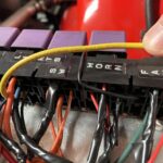
- Yellow wire with gnaw marks..
-
- Damaged orange wires…
-
- More damage…
-
- Damaged blue wire…
-
- Morre damaged orange wires…
-
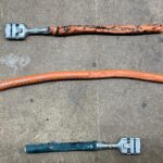
- Cut wire showing damage…
I got started by sorting things out, and assessing what needed to be fixed. The more I looked at this, the more I found “wrong”. And as usual, a small job turned into a more elaborate repair. I found certain wires just did not look good, others were not long enough and the fuse block needed relocating.
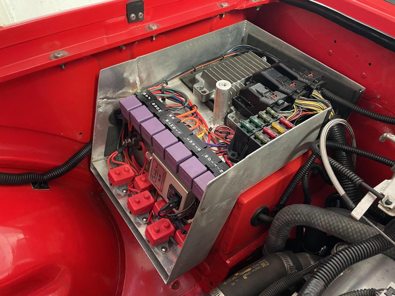
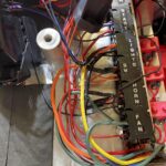
So, after getting the wire cutters, crimpers, soldering gun, solder, shrink wrap, hot air gun, and assorted tools, this job turned into a major redesign. Funny how the hours just stack up when you are having fun! Fortunately the weather was perfect, had some good tunes playing on my vintage 70’s stereo and all was good. This is what the fusebox looks like now…
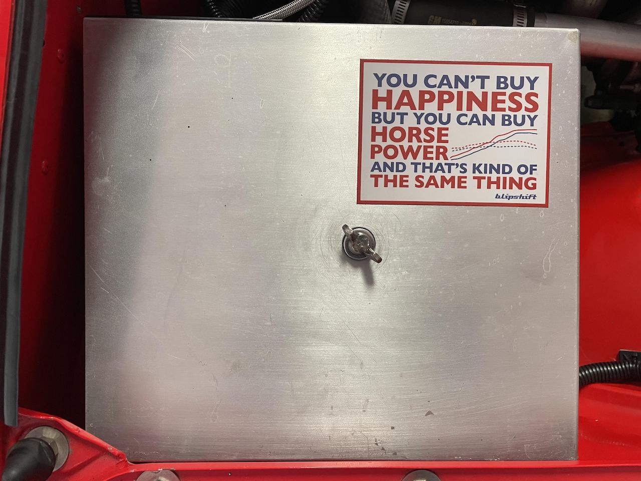
Fusebox lid…
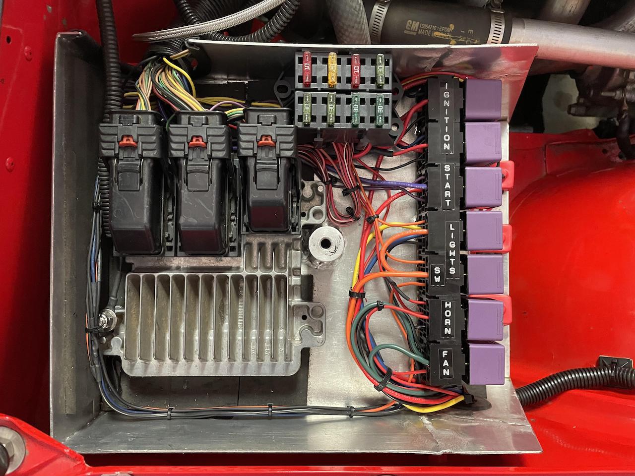
All damage repaired…
So what do we have here?
- On the left with the three big plugs is the engine PCM. You can see the main engine harness top left.
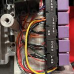
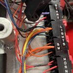
- On the right are the seven purple relays. Ignition, starter, lights, horn and radiator fan controller.
- And the two fuse blocks. They feed various PCM circuits. Some of these are hot all the time; others are switched.
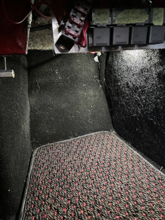
- Below the relays we have 6 breakers, each have a little black button used to reset them in case they get tripped.
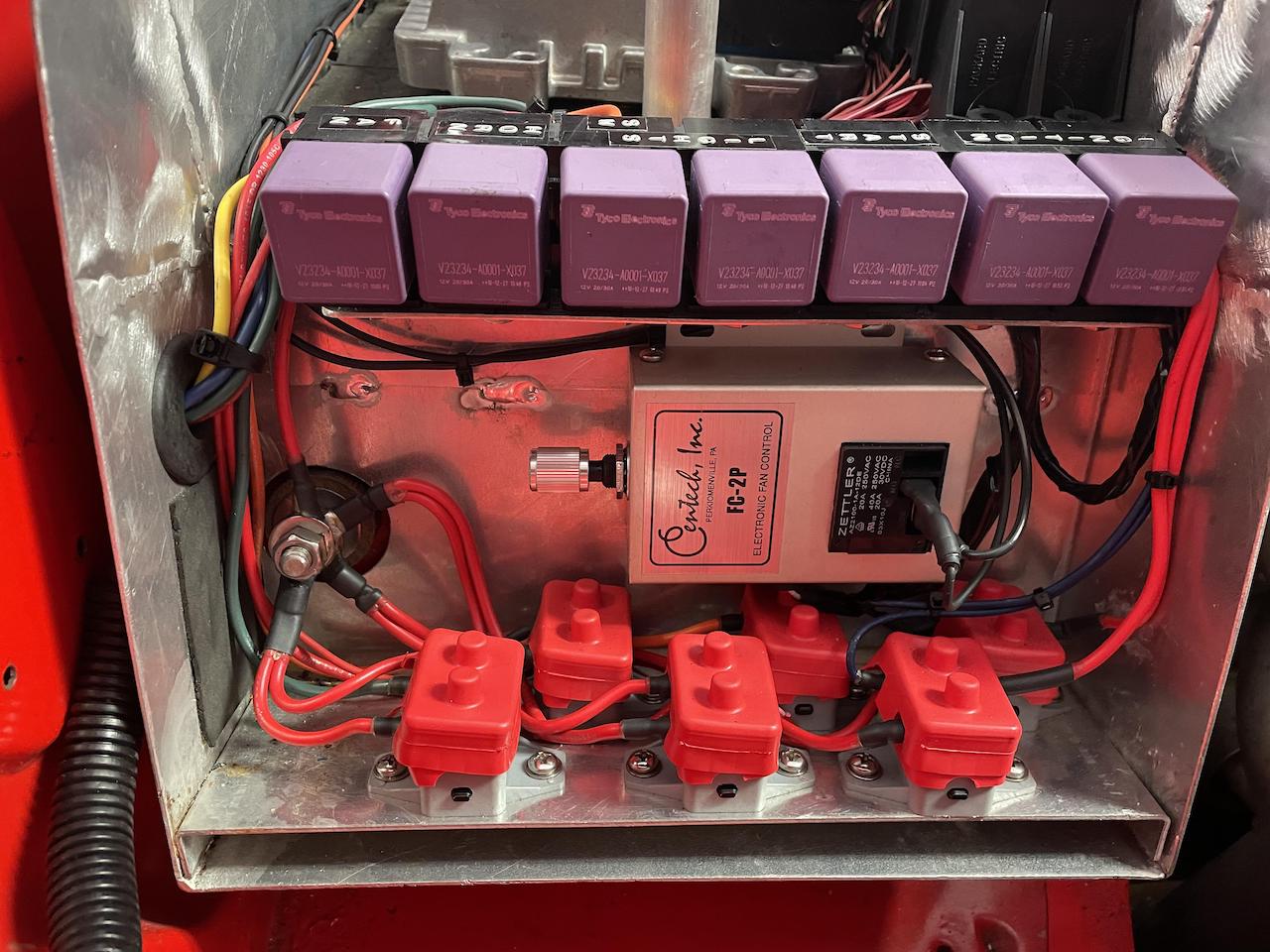
Relays, hot breakers, and fan controller…
On the left is insulated hot post. That post is wired direct to the battery’s hot lead. And from there, power feeds the bank of red breakers. In the middle is the radiator fan controller. It is fed by the temp sensor and it has an adjustable knob that controls when you want the fan to kick in.

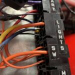
Fuse box from another angle…
And so it goes… I probably have 6 hours on this “repair”. Lots of time spent cutting, splicing, replacing connectors, soldering and adding shrink wrap. Oh and towards the end, a few tie-wraps to make things tidy.And before you start making comments about how “busy” it might look, then I’ll ask: have you ever wired a car before? This is all home-made and this stuff takes time. Finally, this box is not that big so working all the wires through is a pain!
Is it over-engineered? All those relays and circuit breakers and stuff. One could argue this could have been done much simpler, but then what fun is there in all this? 😉 At the end of the day, I plugged the relays back in, re-connected the battery and… No smoke and all works as expected. Overall this was a good weekend!