Tag Archives: bowtie6

bowtie6 Wiring – Part I –

Making a custom wiring harness is an interesting process.  It takes time and careful thought.  Is it for everyone?  No.  This is the second time I’ve wired bowtie6 and this time, I’ve applied several lessons learned from the first time.  Basically:  make things as easy as possible.

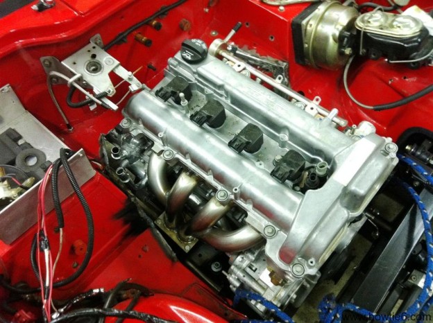
I’ve written previously about all this but I thought it would be nice to give a more in-depth view of the work I’ve done.  Maybe this might be of help for someone, so let me start with the engine.

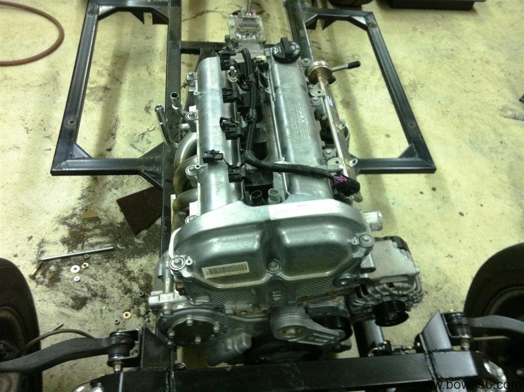
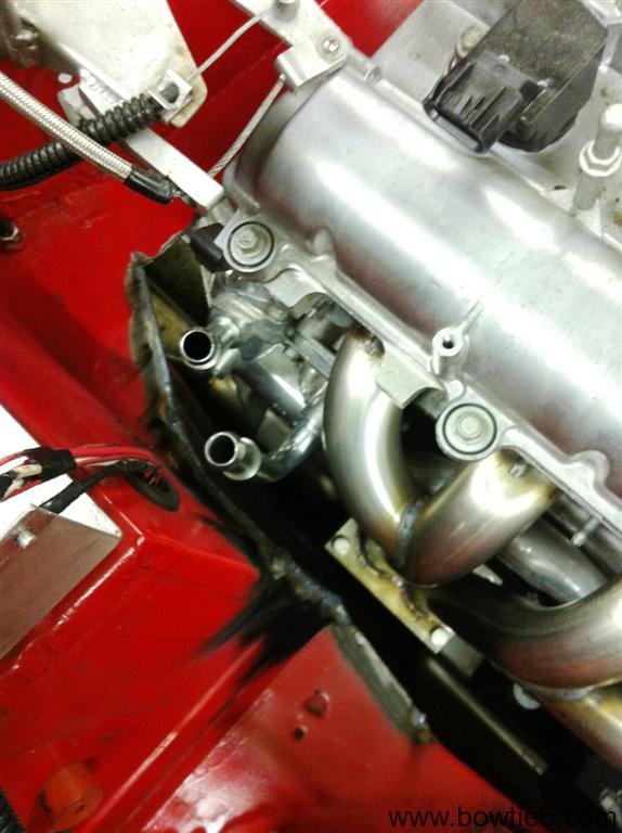
To start with, a factory GM engine harness was sourced.  Contrary to popular belief, one does not need to buy a special harness (they are usually very expensive) to make an EFI engine run.  When properly modified a factory harness is an excellent starting point:  all the sensor plugs are there and the wire is of excellent quality.  Special care has to be taken however, when the harness is extracted from the donor car:  you want to make sure you get all the plugs and pigtails, including the fly-by-wire throttle pedal and its wiring pigtail.

I’ve seen many conversions where folks take an original harness and along with that, the instrument cluster, fuse box, firewall connectors, steering, etc.  This results in a cobbled up, complicated affair.  Why?

  • The donor car’s instrument cluster is kept because modern EFI will not get along with original, mechanical instruments.
  • The steering column is re-used because of the special vehicle anti-theft device that depends on the special tumbler and key to make the engine run.  This is commonly known as VATS – Vehicle Anti Theft System.
  • The original engine fuse box is retained because it is already made and it just “works”.

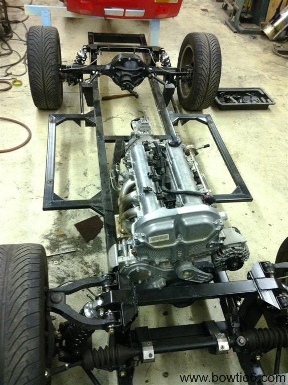
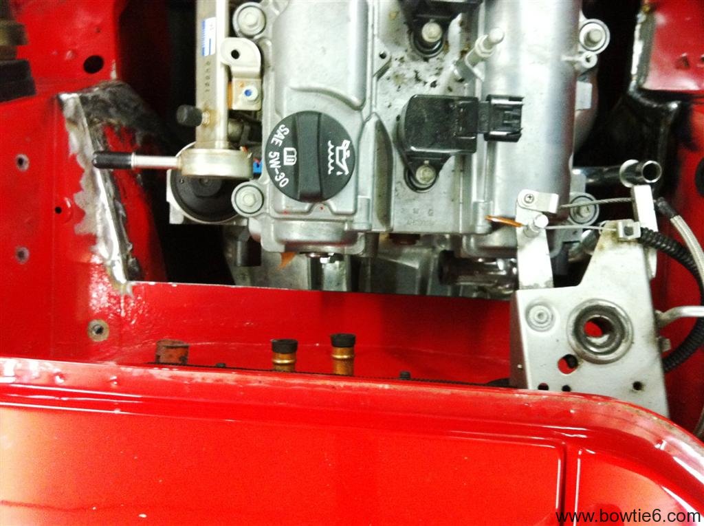
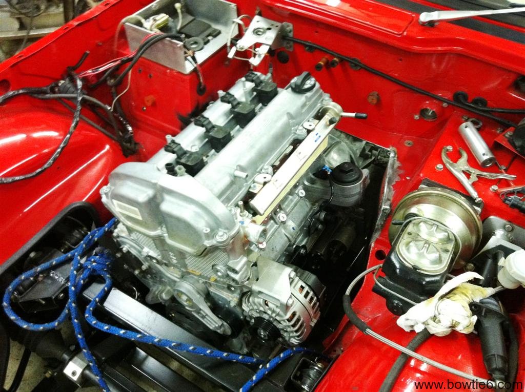
There is a better way.  In my case, the harness was sourced from an Ecotec powered vehicle: a Chevy HHR.  With the aid of the factory service manual for the Solstice/Sky, the harness was simplified by removing unnecessary circuits.  Many wires were shortened and by doing this the harness was greatly simplified and made to fit the engine bay of the TR6.  I did this because again, I’ve seen many conversions where people don’t resize the harness and this gives the engine compartment a very cluttered, busy look.  I’ve also seen conversions where great care has been taken to hide as much of the harness as possible.  This gives the installation a very professional, “factory” look which is not easy to do but if you take your time makes a huge difference.

In the case of the older six and eight cylinder engines the VATS can be disabled by adding a small, inexpensive aftermarket module or by having the ECM modified.  This solves the problem of having to use the original key, tumbler and steering column.  With the previous V6 in bowtie6, I used the aftermarket module.  It basically had a switched hot lead, a ground wire and a wire that was in turn spliced into a pin on the ECM.  With the Ecotec, we did not use a module instead we used software running on a laptop to disable the VATS circuit.

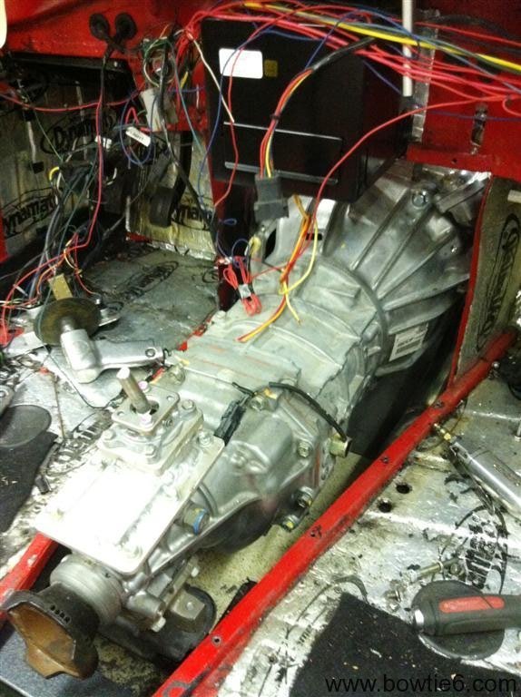
The ECM came from the same donor HHR the harness came from.  This gives a good starting point and is compatible with all the sensors, fly-by-wire throttle, etc of the “original” vehicle.  In my case, I’m running the 5 speed gearbox as fitted to the Solstice/Sky therefore the separate computer used to run the electronic automatic gearbox is removed – this was part of that “simplification” of the harness I mentioned previously.

After all the work of checking every wire for continuity, removing unnecessary wires and length alterations, several loose wires were left:

  • There is one unswitched hot lead that keeps the ECM alive.
  • There are a number of switched hot leads.  These control items such as the O2 sensor, injectors, coils, etc.
  • There are a number of ground wires that must be tied back to either the engine and consequently the engine must be grounded too..
  • The ECM controls the fuel pump.  Therefore there is a wire from the ECM that eventually goes to a relay that energizes the pump.

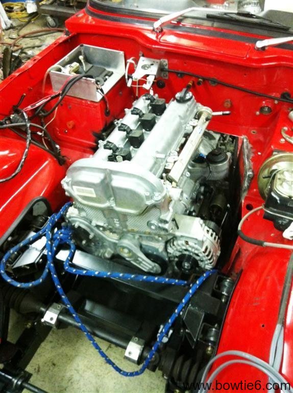
This pretty much wraps up the engine harness.  All this has been done so basically bowtie6‘s Ecotec is all wired up.  Not for the faint of heart, this process alone has taken many hours to accomplish.  There is not easy way out here, but the result is very cool indeed.

So what is left to do?  I’ve taken a different approach this time.  The first time I wired bowtie6, there was one central fusebox where all circuits originated from.  This was fine and dandy.  The fuse box was hidden behind the dash but the problem was twofold: 1) a huge amount of wires coming and going and 2) it was extremely hard to get to.  I once had a fuse blow and it was a hell of a job to find the blown fuse.

This time, the new harness is simpler and has been broken down into three main sections:

  1. Engine compartment:  this section will hold the main circuits managing the engine harness.  I’ve also included the headlights, horn and electric engine fan circuits.
  2. Occupant’s compartment:  basically inside the car.  A separate smaller fuse box will control all switches, instruments and heater.
  3. Trunk compartment:  the last small fuse box where the tail lights, reverse lights, fuel pump and fuel sending unit are all controlled.

In the next installment I’ll have more details about the engine compartment wiring which has been completed.  Stay tuned…

Coilovers on a TR6

When bowtie6 was built the first time, we used coilovers on the rear suspension.  A special bridge was made and welded to the frame to hold the top part of the coilovers and tabs were welded on the aluminium control arms to hold the lower part of the coilovers.  This was nice, the horrible “lever shocks” used on stock TR6’s were removed and all was good.

We thought about using coilovers up front but the way the original Triumph frame is constructed did not allow for a very good placement.  So instead, I used SPAX shocks with upgraded aftermarket “racing” springs.  This setup worked quite well – but with a huge shortcoming.  What shortcoming?

We all know factory Triumph TR6’s require the dreaded “spring compressor” to take the front suspension apart.  This in itself is not a big deal (provided one uses the correct type of spring compressor), however the constant tension from the spring loads up the front suspension something fierce.  This load forces the driver use great effort when turning the front wheels at parking lot speeds.  What??  Well – until you drive a TR6 with coilovers you will have to take my word for it.  With coilovers, one can turn the steering wheel with very little effort.  Huge difference.  Coilovers also allow the use of different spring rates.  One can tune the suspension to his needs very accurately.  Finally, one can control ride height very nicely with coilovers.

The downside is price.  Good quality, rebuildable coilovers are not cheap.  Sure, one can source coiloves from eBay or some half-quality supplier.  Good ones will run you about $400 a pair.  By the time you order the appropriate springs you can have $1000 a set.  But they are worth it!

The following gallery show some pics of my coilovers mounted on the new frame.  There are some pictures of the front as well as the rear suspension, with the solid axle.  One interesting note:  Take a look at the frame:  there is nothing that hangs below the frame line.

Oh and the coilovers, yes, they perform as nice as they look!

bowtie6‘s Frame Failure – Revisited –

I have a few pictures with the rear section of the original frame on bowtie6.  This frame was as about as pristine as could be found when I bought my car several years ago.  There were gussets made and welded onto the frame, as well as reinforcement plates.  Every weld on the frame was gone through and reinforced.  Yet with all this work, after some 15,000 miles the frame failed.

The following pictures show the seam that failed.  Granted the rear is far from stock, but this goes to show that you can weld on the original flimsy frame but this does not guarantee it will survive.  The original frame might be OK for the anemic tractor engine that powers “original” TR6’s, but if you are going to put some real horsepower (and torque) in front of a TR6 then you might want to rethink if the frame will hold up or not.  In my case, sadly the frame gave up the ghost.

The picture above shows the Nissan R200 “long-nose” differential we used.  This diff came from a 280ZX and worked very well – however, it was quite heavy and did not have posi-traction.  The ratio was quite nice – actually a 3.90 to 1 – and this was the reason we chose the 3.80 to 1 for the solid axle currently being installed.  The picture above does not show the coilovers however, that can be found on my “old” website.  The failure happened on the left side (the passneger’s side) and the following picture shows more about it…

In the above picture you see the crack on the tower that supported the coilovers.  Here is another shot:

As you can see, the top section of the frame “lifted” off the rest of the beam.

Finally the above picture shows what the rear of bowtie6 looked like.  The diff is in the centre, with the custom made halfshafts.  The Nissan diff is held in place by the two bridges, the dual exhausts can be seen as well as the rear sway bar.  This was a nice setup and would still be in place except for the crapy Triumph TR6 frame giving away…

Seriously folks.  No joking aside.  I spent a considerable amount of resources on this “original” frame with the work we did to it.  Yet, it failed.  No, I did not abuse my car but I did get down on it in such a way that I could enjoy the upgrades.  For anyone remotely thinking about doing an engine swap using the original frame:  think and double-think what it is you want to do.

The original diff will never hold up.  Eventually after you put enough miles on it, it will fail.  Ditto for the frame.  Once again, the section that failed might have not been “original”, but we had a pristine frame to begin with.  I hope these article and pictures are of value for you.


Final Pics of the New TR6 Frame

Here is a final set of pictures of the new frame serving as bowtie6’s backbone.  The body has now been permanently bolted on, so this is the last set…

Some misconceptions have surfaced as to the origin of this frame.  Suffice to say this is NOT (repeat, IT IS NOT) a RATCO frame.  Those folks produce a nice aftermarket frame but this one is all bespoke and designed for the ECOTEC and the solid rear axle specifically.

Why so many entries on this blog about the frame?  Well, simply put:  I am very proud of it.  My cousin Jim Thompson has put together a very clever, lightweight and strong frame using modern frame-building techniques and materials while being able to retain some of the original TR6 bits.

The front suspension is almost all stock TR6.  The “A” arms, ball joins, steering rack, sway bar, trunions, hubs and rotors are all stock Triumph.  The calipers are Wilwood.  The springs/shocks have been replaced with coilovers.  The coilovers offer several advantages:  no spring compressors, spring interchangeability and the ability to control ride height.  However, they are not cheap but worth every penny.

The rear is all new and it is trick!  The axle is an 8” Ford, custom sized.  It was cut on both sides and custom cut axles have been sourced from Moser.  The gears are from Motive; posi-traction (of course) with a 3.80 to 1 ratio.  Disc rotors and calipers are used on the rear end (with full emergency brake capability using the original TR6 cables and lever), as well as matching coilovers.  There is a four point suspension holding the axle in place with Heim ends on all four control arms.  We tried polyurethane ends, but they did not survive the power from the ECOTEC.  Enter the Heim ends.  Again, only the best have been purchased.  These are precision ground steel (normally used on sprint cars) along with special boots to keep debris out.  Brake and fuel lines are all hand made, hand fitted and hand formed from stainless tubing; with teflon lined, braided lines going to all four calipers.  Again, only the best has been sourced.

This is the second frame built using this design.  The first frame is under Jim’s TR4 and it has proven to be astounding.  It is very stiff – gone is the ‘flex’ that the original frame exhibits.  The new frame is made from much stronger square tubing.  This tubing is a solid square, not a “U” channel with a cap spot-welded as in the original design from Triumph.  I repeat, this is very strong stuff.

Finally, the ECOTEC 2.4 litre engine sits on special plates (on the frame side) that allow the use of the original Solstice engine mounts as well as tranny mount.  The mounts are really nice because they are made with rubber to help isolate vibrations.  Furthermore, the GM mounts have a locking mechanism that if the rubber ever fails the engine will only rock a very small distance and the locks keep it from making undesirable and expensive damage.

Finally some thoughts:

  • I realize this frame has nothing in common with the ‘original’ frame.  My condolence to the purists – but the idea is performance and this frame works and works very well.
  • I’ve read where folks discuss the shortcomings of the AISIN gearbox and say the gearing is all wrong.  Depends what you want to do:  bowtie6 is not built as a drag car.  Yes, first gear is a bit tall and that might not sit well with folks.  I don’t mind it.  From the experience gained from my prior setup and my cousin’s TR4, the car excels like a dream in second, third and fourth.  These three gears are quite simply awesome.  What about fifth?  Well, suffice to say that at speed and in fifth gear all you have to do is punch it and the car will take off.
  • The last thing about the new frame has come as a bit of a surprise to me.  In my cousin’s TR4 the steering “effort” has been reduced significantly.  The “far-back” engine placement has something to do with this.  But there is also the extra pressure of the original spring pushing on the “A” arms that has been deleted.  The new “feel” is much more positive, lightning-quick and a delight to use at parking-lot-speeds.

Here is the final picture gallery of the frame prior to the body being permanently installed.


ECOTEC in a TR6

Today was  a milestone.

bowtie6 had a trial fit of body, new frame and ECOTEC engine.  The following pictures show what this all looks like.

Yes, there has been some “shaping” done to the body.  The area past the firewall was in need of change to make room for the oil filter (on the driver’s side) and the thermostat housing (on the passenger’s side).  For anyone thinking about doing this to a “stock” TR6:  beware.  There will be some work required on the firewall as well as the battery box tray on the stock TR6.  Since bowtie6’s firewall had already been modified, this was a small change.  Under the experts hands of my cousin Jim Thompson, there was some welding involved and voilà – the engine fits.

Once all that work was completed, I mixed up some of DuPont ChomaOne single stage urethane red paint and the bare areas were re-painted.  This took some doing but the result is awesome.  Tonight the new areas are drying and the plan is to bolt the new frame to the body permanently tomorrow.

Well… Here is what an ECOTEC looks like in a TR6 with a custom frame underneath it.  Note how far back the new engine sits.  This change is highly desirable in moving the weight back.  This is indeed a great day!