Author Archives: bowtie6

bowtie6 Wiring – Part II –

Engine wiring is progressing right along,  albeit slow.  This part of building a car takes time!

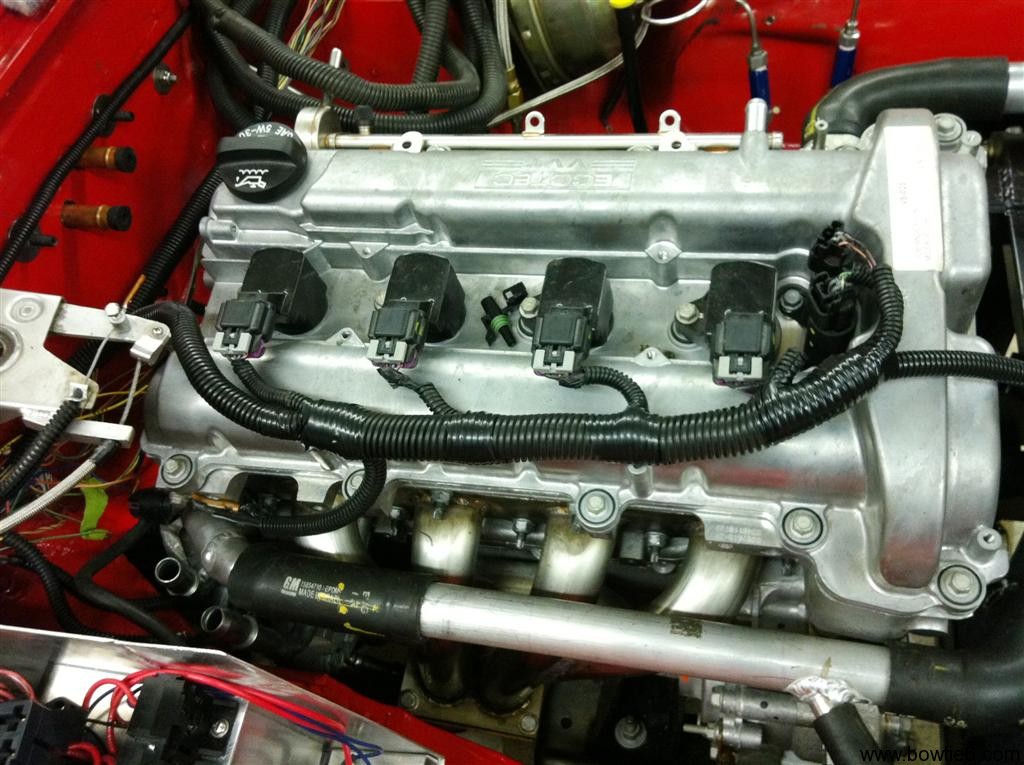
So far the engine harness is complete.  All wires to the ECM have been accounted for and the main looms have been covered with crinkle tubing.  This tubing protects all wires and keeps things looking neat and professional.

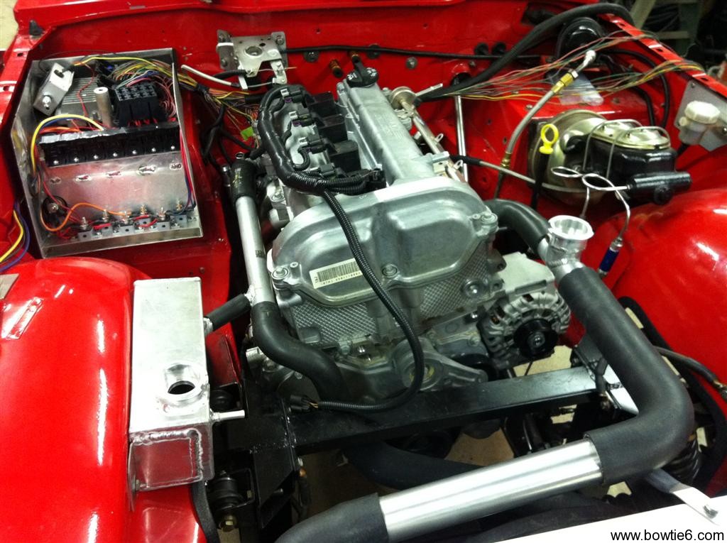
Another engine bay picture showing the fuse box on the left, the coolant overflow tank, coolant lines and brake master cylinder and hydraulic clutch reservoir.  The coolant expansion tank is all hand made aluminium.  Missing from the coolant expansion tank is a small rubber hose going to an overflow tank behind the radiator; also hand made aluminium.  And yes, all the rubber coolant hoses are missing their clamps.  Just haven’t had a chance to get there yet!

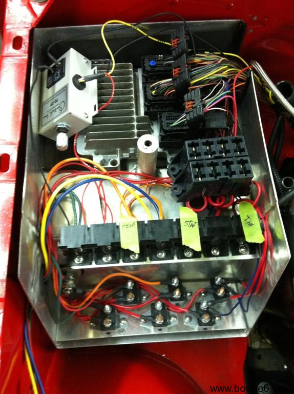
Below, is a close up of the new fusebox.  On the bottom left, you see the new fuse box.  This is where all the relays, circuit breakers and fuses that control the engine compartment reside.  This is what it looks like:

So what do we have here?

Starting from the bottom:  below the box, hidden from view is a post that goes through the firewall.  This post is insulated with a Bakelite insulator.  From this post, wires feed battery power to the circuit breakers.  There are a total of seven circuit breakers; one for each relay.

Above the circuit breakers there are seven relays.  They are used as follows:

  1. Horn relay
  2. Electric Fan relay
  3. Headlight “on” relay
  4. Headlight high/low relay
  5. Starter relay
  6. Ignition relay
  7. Start button relay

Finally above all this are two banks of fuses.  To the left of the fuses is the electric fan controller and below that, the engine’s ECM.

Why so many relays?  The idea here is to use a relay for each device that requires high current, for example the electric engine fan.  The idea is to let the switches run low current controlling the electromagnet in each relay.

I know what you are going to say:  where are the turn signals and parking lights?  Yes, they have been left out.  Not by mistake, but by design.  Underneath the dash will be a smaller fuse box, containing fuses and four relays.  This is the part I’m working on now, and will be featured in the next installment…  Stay tuned.

God Speed, Atlantis…

STS-135 left Launch Pad 39A for the last time today.  A sad day indeed for America.

I feel bad for the thousands of dedicated NASA workers that will be loosing their jobs in the next few days as a result of the cancellation of what basically amounts to America’s space program.  I guess the cadre of “brilliant” politicians that unfortunately run things in America these days – starting from the very top to the very bottom – has decided this is no longer an important priority.  So much of what we enjoy today as “technology” found its origins in the space program.

Perhaps I am a little one-sided.  After all, I remember the day when “One small step for man, one giant leap for mankind” was the news of the day.  I watched it on a small black and white TV – imagine that in today’s world of 50+ HDTV’s…

Critics claim there is not enough money for luxuries such as a “space program”.  I say not.  If only politicians in our country were responsible and instead of pissing our resources on countries that have no desire to be associated with America perhaps we could invest those resources in things that matter:  ourselves.  Don’t take me wrong – I am not an isolationist, but I do have a problem when I read about how such a great portion of our wealth is squandered in “nation building” or corrupt governments all around the world.  The same can be said on the domestic front.

Yes, I guess I’m one of the millions of pissed off Americans that hate to see our glory days in the past.  I am optimistic however, in that good will eventually prevail.  We are in such desperate need of true leadership.  Leadership that can utter words that ignite the imagination of Americans.  Words such as “we choose to go to the moon in this decade and do the other things, not because they are easy, but because they are hard, because that goal will serve to organize and measure the best of our energies and skills, because that challenge is one that we are willing to accept, one we are unwilling to postpone, and one which we intend to win, and the others, too“.

God Speed, Atlantis.  God Speed indeed…


bowtie6 Wiring – Part I –

Making a custom wiring harness is an interesting process.  It takes time and careful thought.  Is it for everyone?  No.  This is the second time I’ve wired bowtie6 and this time, I’ve applied several lessons learned from the first time.  Basically:  make things as easy as possible.

I’ve written previously about all this but I thought it would be nice to give a more in-depth view of the work I’ve done.  Maybe this might be of help for someone, so let me start with the engine.

To start with, a factory GM engine harness was sourced.  Contrary to popular belief, one does not need to buy a special harness (they are usually very expensive) to make an EFI engine run.  When properly modified a factory harness is an excellent starting point:  all the sensor plugs are there and the wire is of excellent quality.  Special care has to be taken however, when the harness is extracted from the donor car:  you want to make sure you get all the plugs and pigtails, including the fly-by-wire throttle pedal and its wiring pigtail.

I’ve seen many conversions where folks take an original harness and along with that, the instrument cluster, fuse box, firewall connectors, steering, etc.  This results in a cobbled up, complicated affair.  Why?

  • The donor car’s instrument cluster is kept because modern EFI will not get along with original, mechanical instruments.
  • The steering column is re-used because of the special vehicle anti-theft device that depends on the special tumbler and key to make the engine run.  This is commonly known as VATS – Vehicle Anti Theft System.
  • The original engine fuse box is retained because it is already made and it just “works”.

There is a better way.  In my case, the harness was sourced from an Ecotec powered vehicle: a Chevy HHR.  With the aid of the factory service manual for the Solstice/Sky, the harness was simplified by removing unnecessary circuits.  Many wires were shortened and by doing this the harness was greatly simplified and made to fit the engine bay of the TR6.  I did this because again, I’ve seen many conversions where people don’t resize the harness and this gives the engine compartment a very cluttered, busy look.  I’ve also seen conversions where great care has been taken to hide as much of the harness as possible.  This gives the installation a very professional, “factory” look which is not easy to do but if you take your time makes a huge difference.

In the case of the older six and eight cylinder engines the VATS can be disabled by adding a small, inexpensive aftermarket module or by having the ECM modified.  This solves the problem of having to use the original key, tumbler and steering column.  With the previous V6 in bowtie6, I used the aftermarket module.  It basically had a switched hot lead, a ground wire and a wire that was in turn spliced into a pin on the ECM.  With the Ecotec, we did not use a module instead we used software running on a laptop to disable the VATS circuit.

The ECM came from the same donor HHR the harness came from.  This gives a good starting point and is compatible with all the sensors, fly-by-wire throttle, etc of the “original” vehicle.  In my case, I’m running the 5 speed gearbox as fitted to the Solstice/Sky therefore the separate computer used to run the electronic automatic gearbox is removed – this was part of that “simplification” of the harness I mentioned previously.

After all the work of checking every wire for continuity, removing unnecessary wires and length alterations, several loose wires were left:

  • There is one unswitched hot lead that keeps the ECM alive.
  • There are a number of switched hot leads.  These control items such as the O2 sensor, injectors, coils, etc.
  • There are a number of ground wires that must be tied back to either the engine and consequently the engine must be grounded too..
  • The ECM controls the fuel pump.  Therefore there is a wire from the ECM that eventually goes to a relay that energizes the pump.

This pretty much wraps up the engine harness.  All this has been done so basically bowtie6‘s Ecotec is all wired up.  Not for the faint of heart, this process alone has taken many hours to accomplish.  There is not easy way out here, but the result is very cool indeed.

So what is left to do?  I’ve taken a different approach this time.  The first time I wired bowtie6, there was one central fusebox where all circuits originated from.  This was fine and dandy.  The fuse box was hidden behind the dash but the problem was twofold: 1) a huge amount of wires coming and going and 2) it was extremely hard to get to.  I once had a fuse blow and it was a hell of a job to find the blown fuse.

This time, the new harness is simpler and has been broken down into three main sections:

  1. Engine compartment:  this section will hold the main circuits managing the engine harness.  I’ve also included the headlights, horn and electric engine fan circuits.
  2. Occupant’s compartment:  basically inside the car.  A separate smaller fuse box will control all switches, instruments and heater.
  3. Trunk compartment:  the last small fuse box where the tail lights, reverse lights, fuel pump and fuel sending unit are all controlled.

In the next installment I’ll have more details about the engine compartment wiring which has been completed.  Stay tuned…
Alumakini on the TR4 – Part II

Last post listed the new modified “Surrey” top on my cousin Jim’s TR4.  Perhaps it is more of an “alumakini” but either way you look at it, it is a quick way to get the sun off your head and make the car a little more enjoyable while still being unique.  Granted, this is not everyone’s cup-of-tea, but if you are looking for “original” then you are in the wrong website.

The following pictures show the “wing” section now fully welded on.  Not only does it look trick, it is fully functional.  The new alumakini provides not only some needed shade but it has made the driving experience much enjoyable:  not as much buffeting and to boost a little downforce provided by the lip.  Nice.

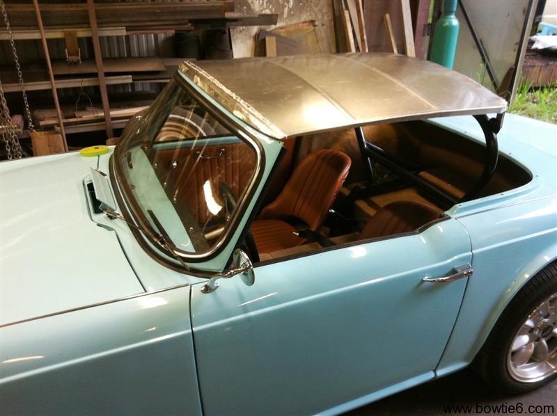
Note the interior in the picture above.  The seats are not “original” Triumph issue.  These have been made from scratch, they are all aluminium.  A local upholstery shop made the covers.  That shop also made the door panels.

The following are closeups of the spoiler.  Sure the top has not been fully finished but you get the idea.  Since this is aluminium, it will need to be etched and then a couple of coats of sanding primer followed by paint.  I’ll have updates when they become available…

Comments?  Drop a line and let us know what you think.


Triumph TR4 Surrey Top – modified

Well – here’s a new one for you…

There is the concept of a Surrey top for a TR4/250.  OK – they are nice but they are hard to find.  They have glass and they are heavy.  They do offer a removable centre section and yes, they are pretty cool.  But here is a variation on the theme…

My cousin Jim’s TR4 has been an awesome car so far.  The ECOTEC has been magnificent providing plenty of power and lots of fun.  However summer is upon us and it gets a little hot to go topless the whole time.  What to do?  Order a canvas top and look like any other TR4?  Nah.  How about this:

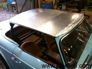
Jim’s TR4 has a rollbar bolted to the bespoke frame on special mounts.  Off the hoop, there are two tabs offering a way to mount the hand-made aluminium “bikini top” shown on the picture at left.  The three “ribs” have been formed on a Pullmax machine.  All total this top is not heavy at all, maybe a couple of pounds.  Not exactly “stock” or “original”, but what the hell.  Jim is a master craftsman and this car is indeed unique.

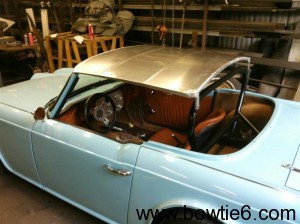
Here is another shot of the new top.  It shows the mounts on the rollbar.  The front attaches to the factory mounts on the windshield frame.  Two bolts will hold that in place.  Jim has made this in such a way that the side glass can be rolled up and it will be perfectly aligned with the edge of the new “top” – and by doing so, the car could be driven with light drizzle and this would prevent one from getting soaked.  This is the inspiration to the new “top”.  Granted, this is not everyone’s cup of tea but what the hell.  It certainly looks trick!

I realize the top looks a little “crude” – it was only made today and has not been totally finished yet.  We were kicking around the idea of fully polishing this top – after all it is aluminium.  The idea would be to make it as shiny as chrome.  Then again, it might just get painted either body colour or some other contrasting shade.  We were also kicking around the idea of covering it with some convertible top canvas to give it a faux look.  One thing we can be certain of:  take a look at the following picture:

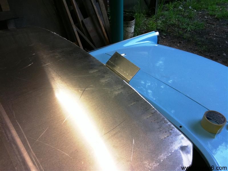
Check out the little tab…  That is a small proof-of-concept:  yes, the top is going to have a mild NASCAR “wing” on it.  This will not only look good, it will provide some downforce at high sped.  And believe me:  the TR4 needs it.  With the extra pop of the ECOTEC, the car certainly can use a few free pounds of downforce.  After all, all the pressure would be transmitted to the rollbar, mounted directly to the frame right above the rear axle…  Pretty cool, huh?