Tag Archives: rear suspension

Refining the Stance

Back to bowtie6’s birthplace for a few suspension tweaks..

First a Little History

If you look at enough TR6’s as I have through the years, you will notice very few (if any) have consistent gaps between the fenders and doors.  To help solve this problem, factory workers at the Triumph factory, added spacers between the TR6 body and the frame.  Quality back in the UK in those days was not great and on top of that, after years of use the frame would sag and the gaps had a tendency to get really bad.  Next time you go to a car show, pay close attention at any “original” TR6’s and you’ll see what I mean.

When Jim and I worked on fitting bowtie6‘s body shell on the new frame, we took a long time carefully fitting the body shell, fenders, doors, bonnet and boot lid.  I remember we actually spent HOURS doing this.  The effort was well worth:  all body gaps came out very consistent.  The downside was we had to make thicker body-to-frame spacers for the rear half of the car.  This essentially slightly “bent” the body and caused the rear half of the body shell to come up and thus exaggerate the distance between the rear tires and the rear fender.

My first set of tires on bowtie6 consisted of four Kuhmo 215/55 tires mounted on those sexy Panasport wheels.  The rears fit just fine; however the edge of the front tires rubbed the edge of the front fenders. I really didn’t any body damage so I found a pair of matching 205/55 tires for the front.  This solved the rubbing problem.

But since building a custom car is not an exact science and one must make compromises, this resulted in the car having a bit of a “rake”.  Not too bad, but when looking at bowtie6 from the side, one would notice the rear tire and fender gap was not ideal.  As a matter of fact, I remember my friend Michael reminding me the rear suspension needed some tweaking.

“Drop it down an inch”, he said.  Yeah, umm-hu.

New Tires

As noted in a previous blog article, this summer I bought a new set of tires.  This time I ditched the staggered sizing in favor of a square setup:  I bought from The Tire Rack, four 205/55 Yokohama summer-only tires.  Well, with the different tire height (remember, we went from 215/55’s to 205/55’s) the rear fender gap got really bad.

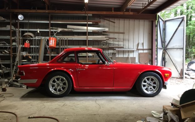
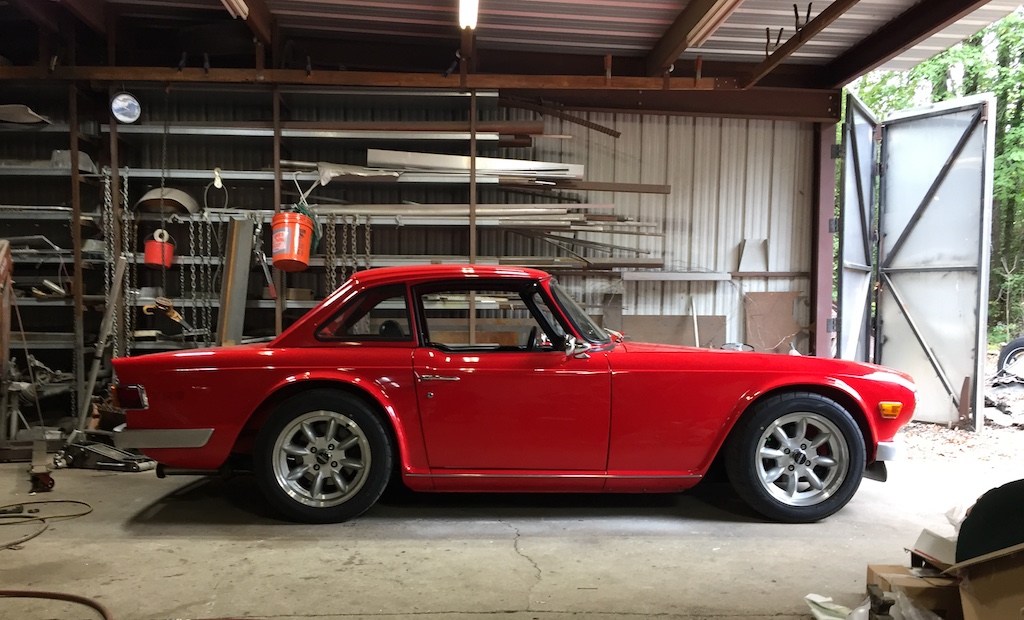
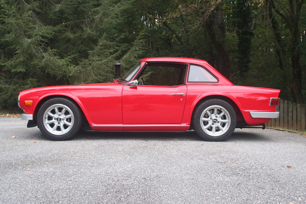
Before… (for the “after”, see the last photo at the bottom)

See what I mean?  The rear gap was not quite right.  Well, I was not about to go digging out the body/frame spacers because this would throw the body gaps all to hell.  Fortunately, Jim was able to come up with a small but effective solution to the problem.

Solution and New Stance
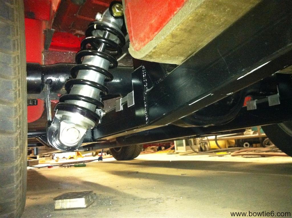
When Jim modified the rear axle to handle the coilovers, he made vertical mounting pads for them to bolt on to.  You can see the outline of the pads in the photo above.  Today, we took all this apart and added an extender to the pad.  This extender basically moves the axle about an inch upwards.

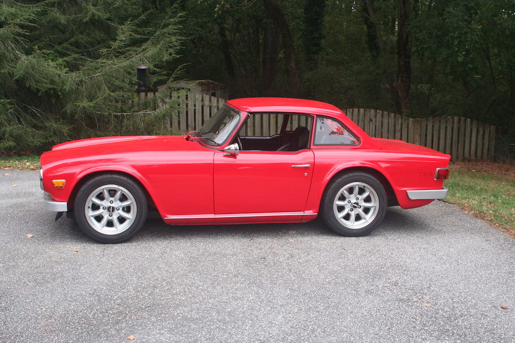
And the result is amazing!

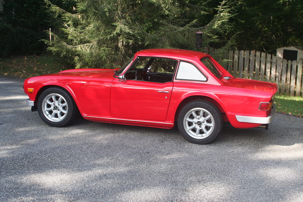
Before the tweak…

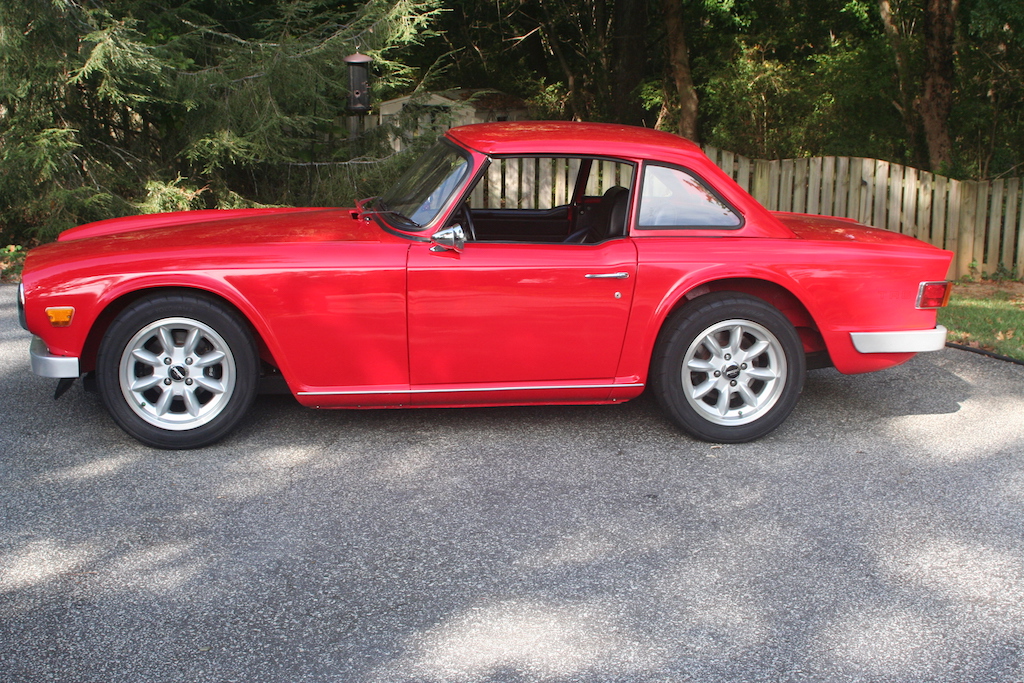
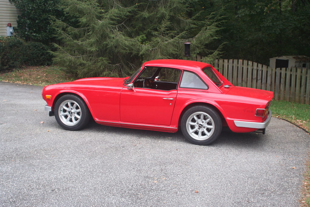
After the tweak…

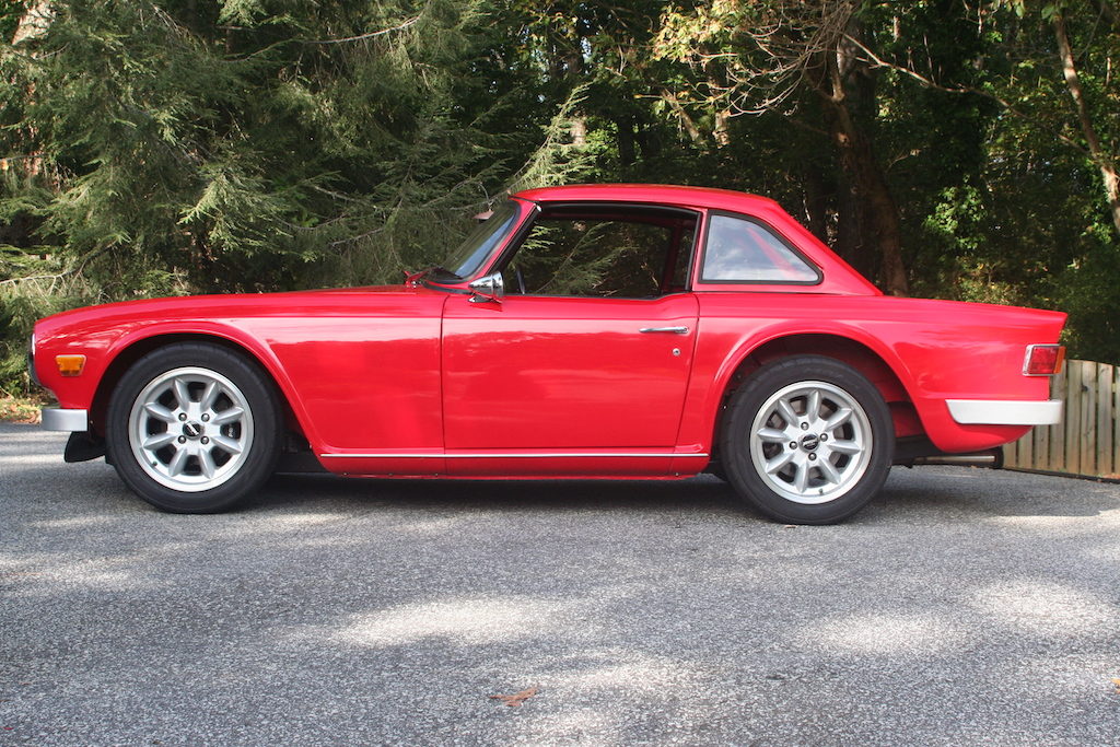
And there you have it!  The rake is almost gone.  Jim and I measured the end result and there is about a quarter of an inch difference between the and of the front fender and the start of the rear frame along the center of the body shell.  The gap has been reduced dramatically and overall bowtie6 has a much more refined stance.

Before…

After…

After… (see above for the “before” version)

bowtie6‘s Frame Failure – Revisited –

I have a few pictures with the rear section of the original frame on bowtie6.  This frame was as about as pristine as could be found when I bought my car several years ago.  There were gussets made and welded onto the frame, as well as reinforcement plates.  Every weld on the frame was gone through and reinforced.  Yet with all this work, after some 15,000 miles the frame failed.

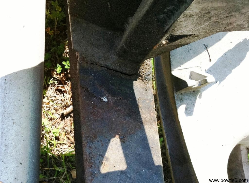
The following pictures show the seam that failed.  Granted the rear is far from stock, but this goes to show that you can weld on the original flimsy frame but this does not guarantee it will survive.  The original frame might be OK for the anemic tractor engine that powers “original” TR6’s, but if you are going to put some real horsepower (and torque) in front of a TR6 then you might want to rethink if the frame will hold up or not.  In my case, sadly the frame gave up the ghost.

The picture above shows the Nissan R200 “long-nose” differential we used.  This diff came from a 280ZX and worked very well – however, it was quite heavy and did not have posi-traction.  The ratio was quite nice – actually a 3.90 to 1 – and this was the reason we chose the 3.80 to 1 for the solid axle currently being installed.  The picture above does not show the coilovers however, that can be found on my “old” website.  The failure happened on the left side (the passneger’s side) and the following picture shows more about it…

In the above picture you see the crack on the tower that supported the coilovers.  Here is another shot:

As you can see, the top section of the frame “lifted” off the rest of the beam.

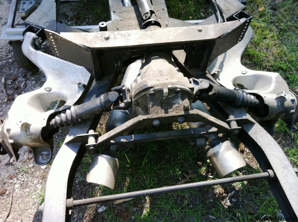
Finally the above picture shows what the rear of bowtie6 looked like.  The diff is in the centre, with the custom made halfshafts.  The Nissan diff is held in place by the two bridges, the dual exhausts can be seen as well as the rear sway bar.  This was a nice setup and would still be in place except for the crapy Triumph TR6 frame giving away…

Seriously folks.  No joking aside.  I spent a considerable amount of resources on this “original” frame with the work we did to it.  Yet, it failed.  No, I did not abuse my car but I did get down on it in such a way that I could enjoy the upgrades.  For anyone remotely thinking about doing an engine swap using the original frame:  think and double-think what it is you want to do.

The original diff will never hold up.  Eventually after you put enough miles on it, it will fail.  Ditto for the frame.  Once again, the section that failed might have not been “original”, but we had a pristine frame to begin with.  I hope these article and pictures are of value for you.


Ecotec Motor Mounts, Rear Suspension and Headers…

Oh yeah!  Today we have some really cool pictures.

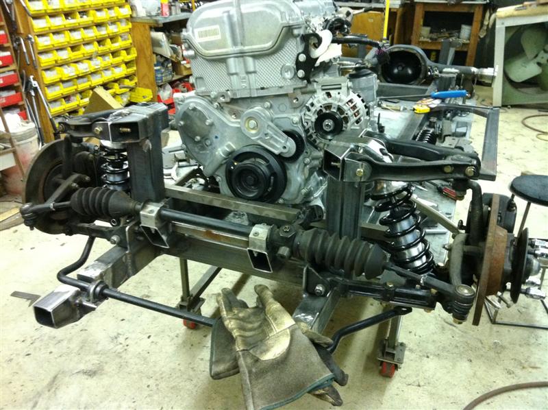
The frame is starting to really take shape.  The front suspension is pretty much done.  The following picture shows how things are looking right now.  The front suspension towers are in place, coilovers and lower plates.  No more spring compressors, just the real deal:  coilovers.  The front sway bar has also been located as well as the steering rack.  The square stock bar in front of the pulley is not part of the build so don’t wonder what that is there for.  Finally, there are quite a few welds that need to be finalized – right now there is a lot of stuff that is tack-welded.  Oh…  And the Ecotec is now mounted on the table in order to finalize where it will be residing.

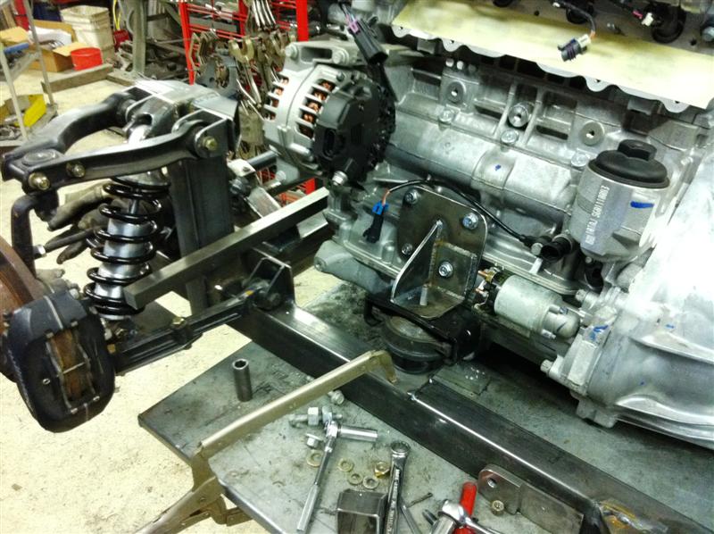
The next picture shows the driver’s side motor mount.  Since the frame is being made from scratch, we can use the original mounts.  Nothing wrong with them.  However, these are the ones that attach to the frame not the ones on the engine block.  Those would have been way too wide, so new plates have been made.  Look closely, and you will see the factory intake has been removed.  When fitting an Ecotec on a TR6 the original intake has to go – otherwise it will be in the way of the steering assembly.  There will be a custom-made intake so more room can be dedicated to the steering.

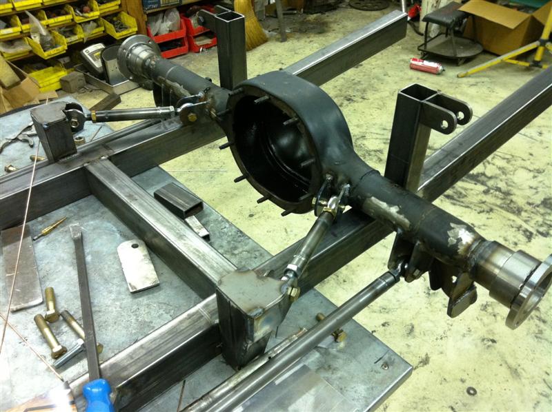
Next, let’s take a look at how the rear suspension is looking.  This is really trick.  Here we have a four point suspension also with coilovers.  They are not in place but they are identical to the fronts – however the spring rates are different.  The control arms are all finished with heim-ends; my cousin used polyurethane ends on the TR4 but they soon failed.  I’ll have a future article on that.  The diff is not in place yet nor the axles.  This will all be ordered soon.  The plan calls for a 3.80 to 1 axle with posi-traction.  This will give the car a great response at speed.  Special note must be taken:  this is not a drag car, instead it is being designed to excel at speed.  This is what the rear looks like:

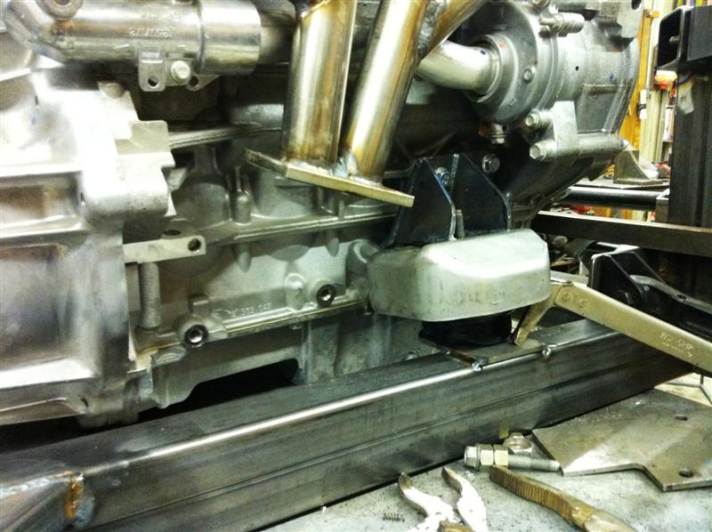
Finally today’s real work of art:  the new headers for the Ecotec.  The headers have been hand-made, from stainless tubing.  The flange on the block is GM – they sell a special flange that gives an excellent base for the headers; there is also a GM flange similar to this, for the intake.  The header does not have a bung for a O2 sensor – that will be placed on the bottom tubing, after the flange.  These headers should flow very nicely and since they are very close to the block, it will prevent the body from having to be cut.  All this stuff is being built for a reason!

And finally, another shot of the lower part of the headers, showing the motor mount on the passenger’s side.  This mount has a special heat insulator – that is stock from the factory due to its close proximity to the header.  Cool, huh?

Like I said before, things are being tack-welded now.  Much easier to cut a tack-weld than if it were permanently welded in case we have to make adjustments when the body is fitted.

Comments?  Questions?  Drop me a line…