Category Archives: 1. bowtie6

bowtie6‘s Tilt Steering

Aside from the Ecotec, coilover suspension and new frame the most anticipated improvement made on bowtie6 has been the new tilt steering mechanism.  On the first iteration with the V6, the steering wheel just did not feel 100% perfect for me.  It was very close, but it sure would have been nice to make it dead nuts accurate.  Solution:  tilt steering.

This one is going to be very hard to replicate using the factory steering.  In our case, the entire steering column was replaced with a much simpler design (click here for more).  This allowed freedom to pretty much do anything.

So basically what we have is a new aluminium  tube with bearings on either end.  Inside that is a shaft with a threaded end where the steering wheel gets bolted on.  On the firewall is a fixed bearing that allows a pivot.  The steering rod goes through it and that eventually ends up at the rack.  Along the way are two stainless Borgeson “U” joints – one even has a built in shock absorbing element that keeps road vibration out.  We used the u-joints, not the “rag” joints because the u-joints are more durable.  This is what it looks like:

At first, I guess the question is “what is the big deal”.  Well the aluminium tube I mentioned above can be seen going through the dash.  It is fixed and the actual steering shaft is inside the tube.  On the right side, behind the turn signal housing is a little lever.  Pull down on the lever releases the mechanism and the steering shaft glides along the two tracks you can see in the opening in the dash.  Here is a side view:

The wheel hub is on the left, you can see a brass spacer followed by a Nylatron spacer.  These are made to allow a smooth movement and durability.  Then is the turn signal housing and inside the dash opening the adjustment lever and the “tracks” where the steering shaft travels on.  The tracks are bolted to the original dash mounting screws on the body.  It is hard to describe but believe me it works!

My cousin Jim designed this entire steering shaft and built it from scratch.  The idea here is for making this as simple as possible – however this has many challenges!  Among them, how do you get a turn signal switch and have it operate as “original”?  Well, here is the solution:  inside the steering tube, on the steering shaft the factory TR6 turn signal activator ring was retained.  This is a clamp-on affair with a little ridge that causes the turn signal leg to trip when it is in either the “left” or “right” direction.  The switch itself is stock TR6 except that it has been modified to fit inside that little aluminium box.  There are two screws that hold the switch in place.  This is all wired up to my custom wiring harness and includes fully functional “left” and “right” turn signal indicator on the dash (you can see them at the top of the instruments above).

This is what the firewall side looks like, seen from the inside.  You can see the Borgeson joint, just above the firewall bearing.  The Borgeson joint is what enables the “bend” to happen when the steering shaft tilts up or down.

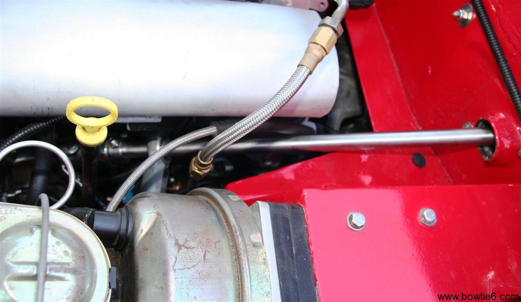
This shows the steering shaft under the hood:

This is the stainless shaft that resides inside of the aluminium tube on the inside of the cab looks like.  All this eventually ties into the steering rack.

In the final analysis several concessions had to be made in order to have “tilt” steering.  The most severe was cutting the dash as shown in the photos above.  This really hurt because I have been very proud of just how nice it is.  But, it has been a great tradeoff.  Being able to adjust the steering has been priceless.  Now, I have the 13″ leather Mountney steering wheel in the exact position I like.

Is this something that can be replicated?  With the original steering it would be very difficult.  I guess an option would be to somehow graft a donor car steering column but that not only takes up space but looks very cluttered.  But, to each his own.  I like the simplicity of mine, and it is very easy to service.

Hope this sparks some ideas…  🙂

Carpet Kit for a TR6

One of the many things that gets overlooked when doing an engine transplant like mine is figuring out how to handle a small issue such as carpet.  In order to fit the Ecotec, we had to modify the transmission tunnel and made a few alterations to the floor.  You can see more about that by clicking here.  That link shows pictures of the body work done long ago when we first did the V6 conversion.

With all this work as well including the new all aluminium transmission tunnel, any “original” carpet kit simply does not work.  So how do we solve this issue?  Some folks wold perhaps send the car off to somebody that would do a custom interiors.  That would be too easy.  We made our own.

Fist, the entire floor and new transmission tunnel were generously covered with DynamatExtreme.  This stuff is not exactly cheap, but it does the job very nicely.  There are several less expensive ways to cut corners here, but I am partial to the real-deal so that is what I used.

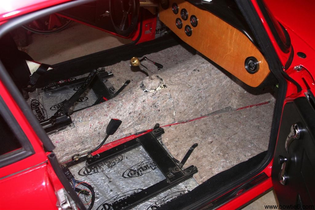
Next step is to get a nice base to the carpet.  Fortunately, there is an industrial automotive carpet supply warehouse not far from my house.  They have any carpet material imaginable.  I bought several yards of this backing material for about five bucks per yard.  This is 36″ wide material so you have to plan accordingly but for the price it is hard to beat.  I’ve lined all the inside of the cab and trunk.  This is what the cab looks like:

Installing this is not a real problem.  Get a pair of sharp scissors and a box cutter blade and you will be in business.  I used contact upholstery glue to hold the stuff in place.  Word of caution:  there are several types of glue.  You can go to Home Depot or Lowe’s and spend big bucks on 3M contact cement – that stuff will set you back about $14 per can.  Or, do like I did and get the adhesive at the carpet supply warehouse.  They had this stuff for about $7 bucks a can.  Can’t beat that.  This takes a little time to get cut and glued down, but the result turns out nice and this helps keep noise and heat out.

Next comes the actual carpet.  I bought a non-woven material that can be cut and shaped very easily.  Best of all, it won’t “unravel” like regular carpet does.  The material I bought comes in 72″ width and is not too terribly expensive either.  Why go with this?  Well, for one it is easy to install and best of all since it is cheap it can be replaced when it gets worn or looks bad.  I used this material the first time I did the interior and that was five years ago.  It held up extremely well.

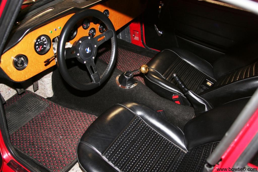
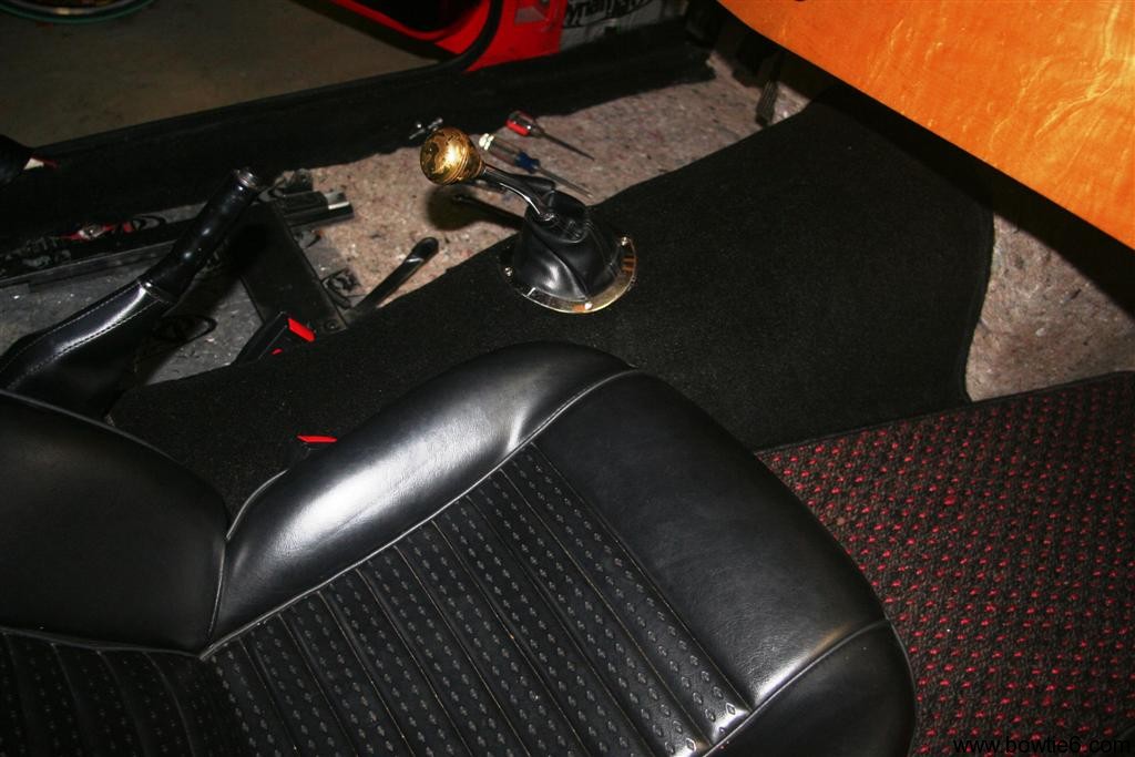
The picture above shows several things (sorry for it looking “dark”).  The carpet is now covering the transmission tunnel.  The handbrake boot came from an “original” carpet kit.  That was about the only decent piece in the set.  At any rate, I saved and used this piece because it covers the handbrake handle.  Basically I cut the section and placed that on the tunnel.  Then on the new carpet I cut a square hole big enough to allow the boot to fit through.  Glue it down and voila!  It looks “factory”.

The shifter boot is straight out of Street Rod 101.  You can get these at any street rot speedshop.  It has four countersunk screws and the boot is vinyl.  The shifter knob however is special.  My cousin chucked on the lathe a solid piece of brass barstock and shaped it on the fly.  This thing is heavy, but there is a valid reason for this:  it helps shifting.  Yeah, I’m sure you’re calling bullshit but this thing does work!

The seats are covered in “stock” foam and fine, exotic vinyl.  Not exactly the fanciest or the most fancy but they do the trick.  My good friend Mike was kind enough to cover them for me and they have held up quite well after 5 years of use.  I reckon I could have sprung for leather but those are pricey and questionable in the durability department.  Maybe one day I’ll have one of those “professional” outfits do the seats.  For the time being, these will do just fine, thank you.

Finally on the floor are my trick sisal mats.  Those were custom made for me by a South Carolina based company and they did an excellent job.  And yes, those are little red dots woven in.  They match quite nicely the exterior of bowtie6.  These mats are extremely easy to keep clean and look awesome.  Yes, they might be a little “retro” but it fits the personality of my car.

So there you have it.  I still have some work to do on the firewall and I’ll have an update on that soon.  The point I’m trying to make here is that if you think outside of the box you can get a real cool look and feel.  It might not be “original” but who cares?  I made this myself, it looks great and it did not cost a bunch of money.

ECOTEC Drive by Wire

All modern GM engines (LSx’s, Vortec’s, Ecotec’s, etc.) use the so called “drive by wire” or “fly by wire” throttle bodies.  Long gone are the days of actuating the throttle butterfly by mechanical means – ie, a cable – from the accelerator pedal to the throttle body.  Instead, the throttle butterfly is now controlled by a servo motor actuated by inputs from an electronic accelerator pedal attached to the ECM.  If you Google any of these terms, you will get plenty of info on how it works so I won’t go into the details.  This hangs up a lot of folks doing conversions and they end up using a throttle body with a cable.  We did not want to go that route.  What I do want to show here is how we solved some of these problems on bowtie6 while still retaining all the electronics.

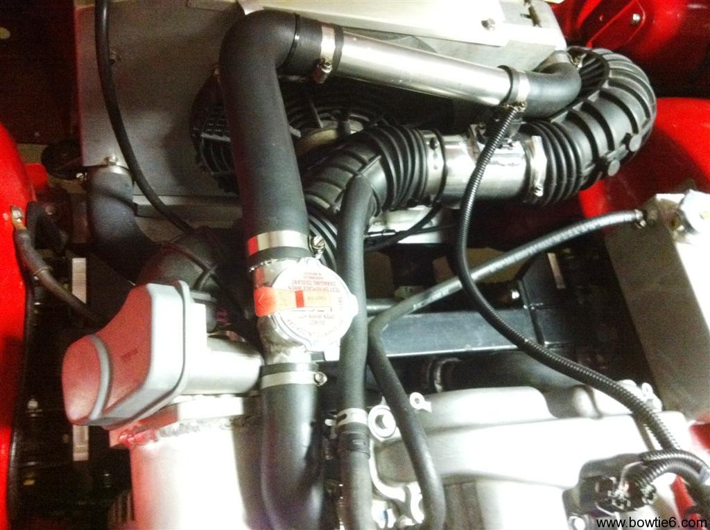
The following pictures show what the throttle body looks like.  Since we are running a completely different intake manifold from the Solstice, the throttle body is bolted on a special flange on the new intake.  We could have used the plastic intake, but that would have been a major hassle with the steering mechanism.  In front of all this is flexible rubber tubing recycled from the Solstice.  The silver tube midways is the special housing for the MAF sensor and ahead of that (hidden by the radiator and ahead of the rubber bend tubing) is a K&N air filter.  On bowtie6, the air filter sits ahead of the radiator, right behind the factory grille allowing the coldest air to be pulled in.  However, this all comes at a price:  the MAF must be re-calibrated because of all the bends in the airflow.

This is what the whole shebang looks like…

Here is a closeup of the throttle body…

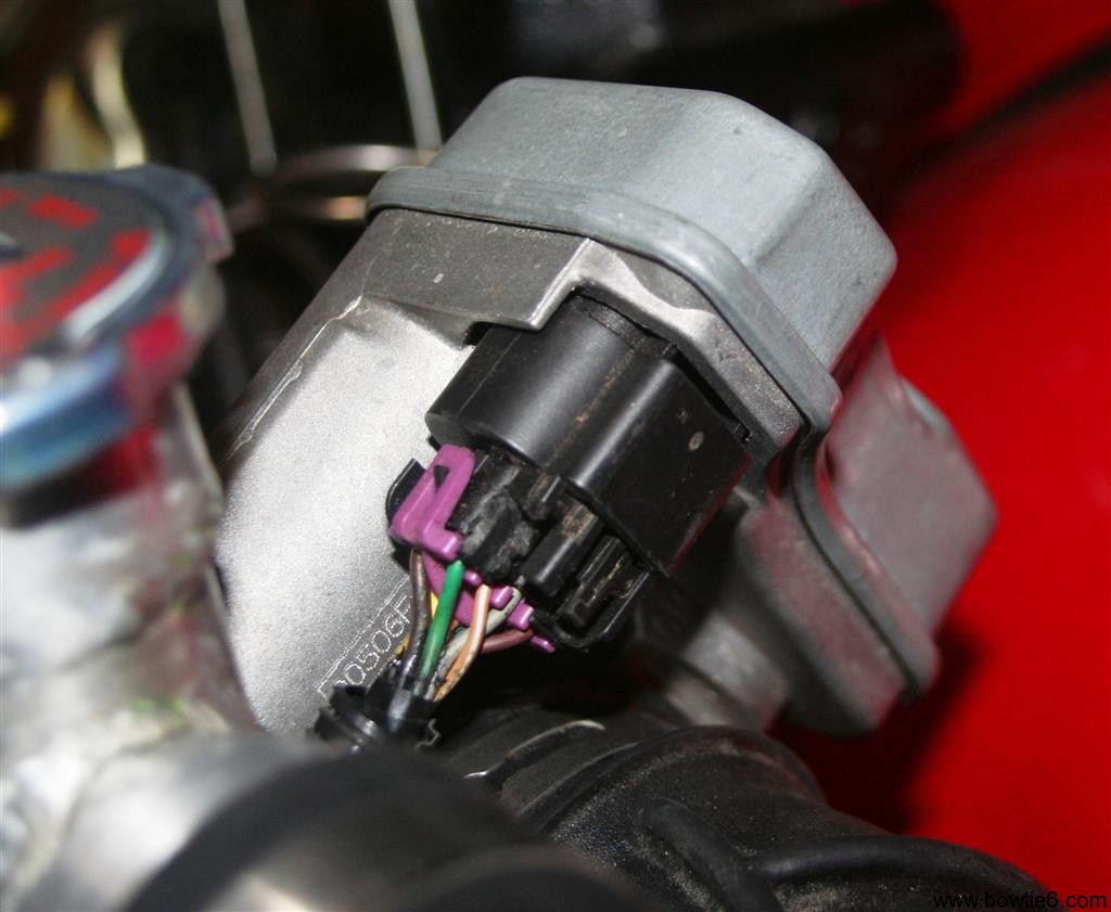
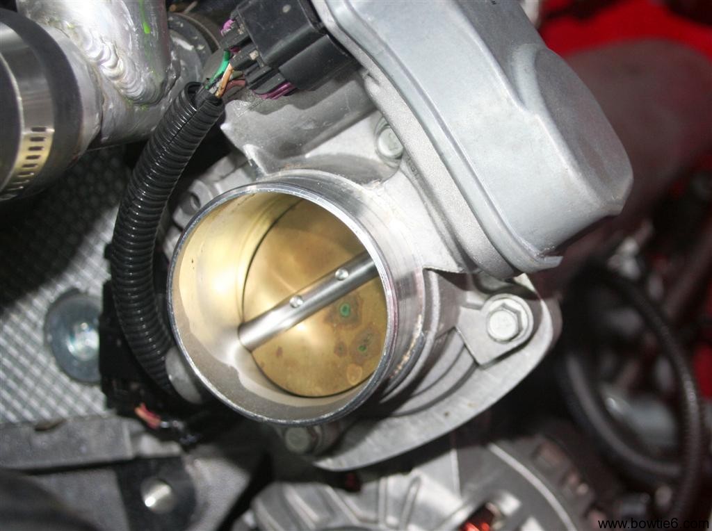
This is the stock throttle body as found in the Pontiac Solstice/Saturn Sky.  The grey plastic cover hides the stepper motor and the rest of the mechanism that opens and closes the butterfly activated by the ECM.  Here is another picture from the back of the throttle body showing the connector plug with the wires coming from the ECM.

Finally, here is what the inside of the throttle body looks like.  I reckon this all could eventually be fully polished, however I have doubts on how great that idea would be and whether there would be any benefit in that.  At any rate, it is what it is…

As you can see, there is no cable.  This is all controlled electronically.  Right before ignition, the engine does a “test” of the throttle body and yes, there is a split second delay.  If you pay attention, one can actually hear the stepper motor in the throttle body opening the butterfly to WOT and then back to the closed position.  Then ignition occurs.

If you are looking at all this and wondering where the traditional Idle Air Motor is then you are correct:  it is not here.  Idle is handled by the ECM and TPS.  From there, the butterfly opens to control idle.

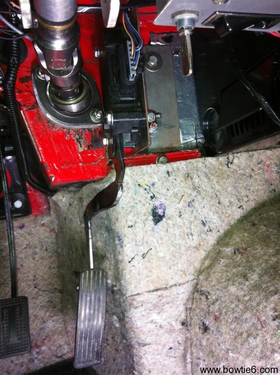
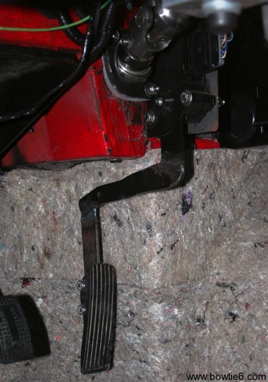
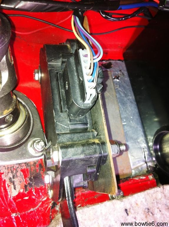
Controlling all this requires the special matching throttle pedal.  Here is where things get interesting.  There are quite a few versions of these throttle pedals.  For example, Vortec engines have a certain version, GTO has another and Vette’s have yet another.  Along with that, some are all plastic, others are plastic with metal arms, some have 6 wires and some have 8 wires.  In our case, we used a throttle pedal used in the 2.4 Ecotec powered HHR.  The advantage of this pedal is that the actuator arm is metal, and thus can be cut and shaped to fit the location where it is mounted in.  This is what the one in bowtie6 looks like:

Sorry for the boring gray background (this is a sound insulating material glued to the Dynamat Extreme prepared body) but thought it be best to take this picture before I install the black carpet.  Otherwise we won’t be able to tell squat of what this looks like.  Some things to keep in mind about what you see above:

  • The pedal is still a little “crude”, if you will.  This is version 1.0 of the pedal.  So far even though it works perfectly there is some issue with the exact angle of the plastic pedal itself.  As you can see it is still a bit too straight.  I am planning to fine tune it by angling it a bit – the top needs to be brought down a little and the bottom needs to come up.  I just need to make up my mind on how far to make the angle.  It is also a bit long.  As you can see the top is rounded somewhat.  I need to make the bottom rounded as well.
  • The “travel” takes some getting used to.  This is a small compromise but this has to be retained because this is the way the ECM is expecting the signal to be sent.  If you look closely, there is a plug at the top with some wires going into a housing.  This is where the potentiometer that translates pedal movement into a signal resides.  This is what tells the ECM what throttle angle is being requested.
  • Looking at the picture above would lead you to believe the metal “arm” hits the red body of the car at the top, right?  Nope.  The travel is not great at all and the arm does not touch the body at WOT.  I also own a 2.4 Ecotec powered HHR and the throttle travel there is equally short.  However, believe me – this is not a problem at all when driving the car.  The throttle has the same “look and feel” as a mechanical system does.  It just takes a little getting used to.

For those of you considering an Ecotec conversion, this is going to be a very important issue to figure out.  Like I said before, there are many different varieties of thottle pedals.  I have read where there are some that are actually meant for the V8’s.  Once you settle on the correct pedal to use, placement will require some adjustments.  Mine is close but not quite 100% perfect yet.

There is yet another alternative and that is to use a Lokar fly-by-wire system.  I think these were introduced at SEMA earlier this year.  I have done some reading about them but I have not seen one in person and have no idea how helpful it would be.  On the downside too is the price – they are quite price.  The stock GM stuff can be had for a few bucks at your junkyard or from auction on eBay.

TR6 Trunk Liner Kit

The “original” TR6 trunk liner calls for this ugly cardboard material used to dress up the sides of the trunk.  There is also a piece that hides the tank.  In my case I wanted to try something a little different.  Something more modern and durable.

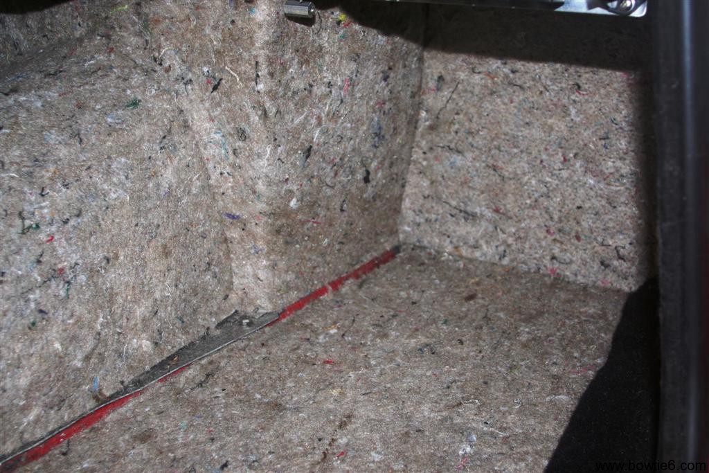
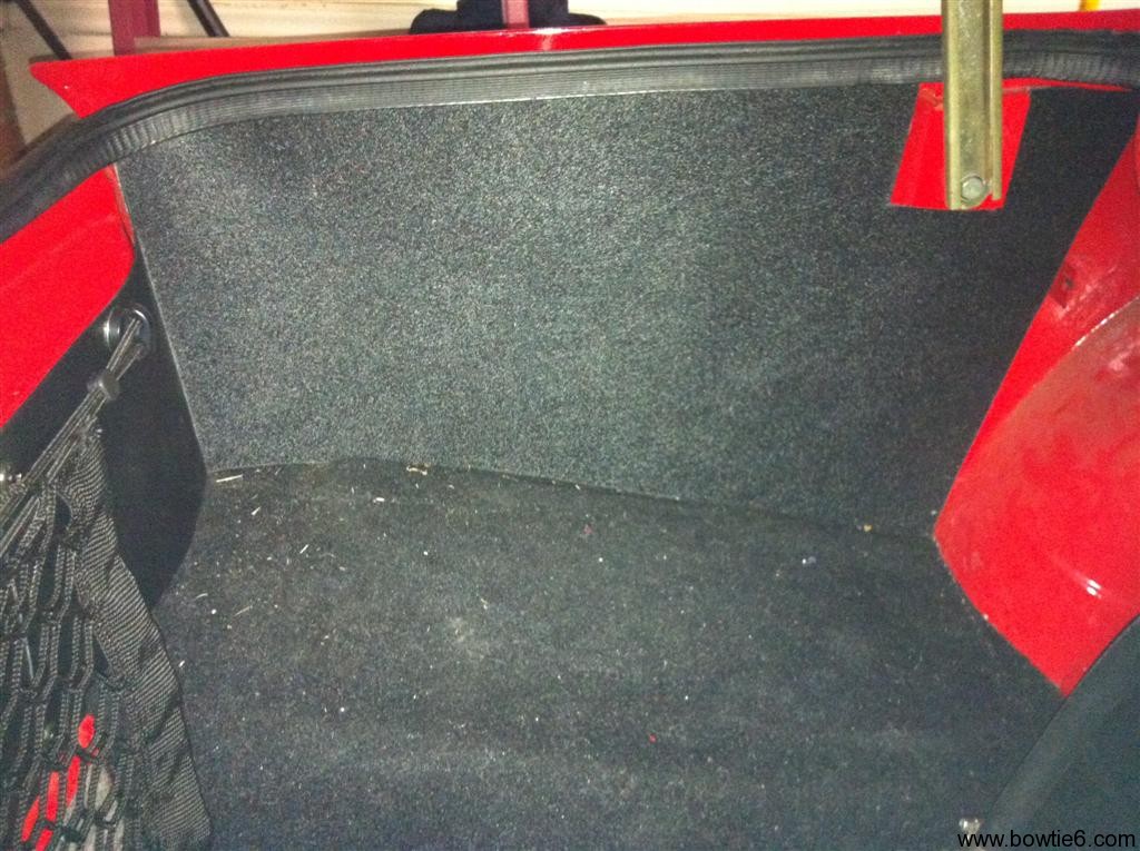
There is a local automotive interior supply warehouse close to where I live.  This is where I bought the sound deadening carpet backing material, the carpet and the black plastic material I used for the trunk liner.  This material is easily cut with scissors, although I used a shear (normally used to cut sheets of metal) to get crisper edges.  In order to form this material one can use a break and this plastic has enough “give” to make some very sharp edges.  The result looks very neat and is a zip to make.  Take a look at the driver’s side trunk panel:

I made the edges just a tad longer and this fits quite tight.  On the top side (near the trunk gasket) it fits quite tight and once you lower the gasket over the edge it actually helps support the plastic liner in place.  The greatest advantage is that on the back of the trunk it helps hide all the wires going to the tail lights.  You can see that more so in the next picture:

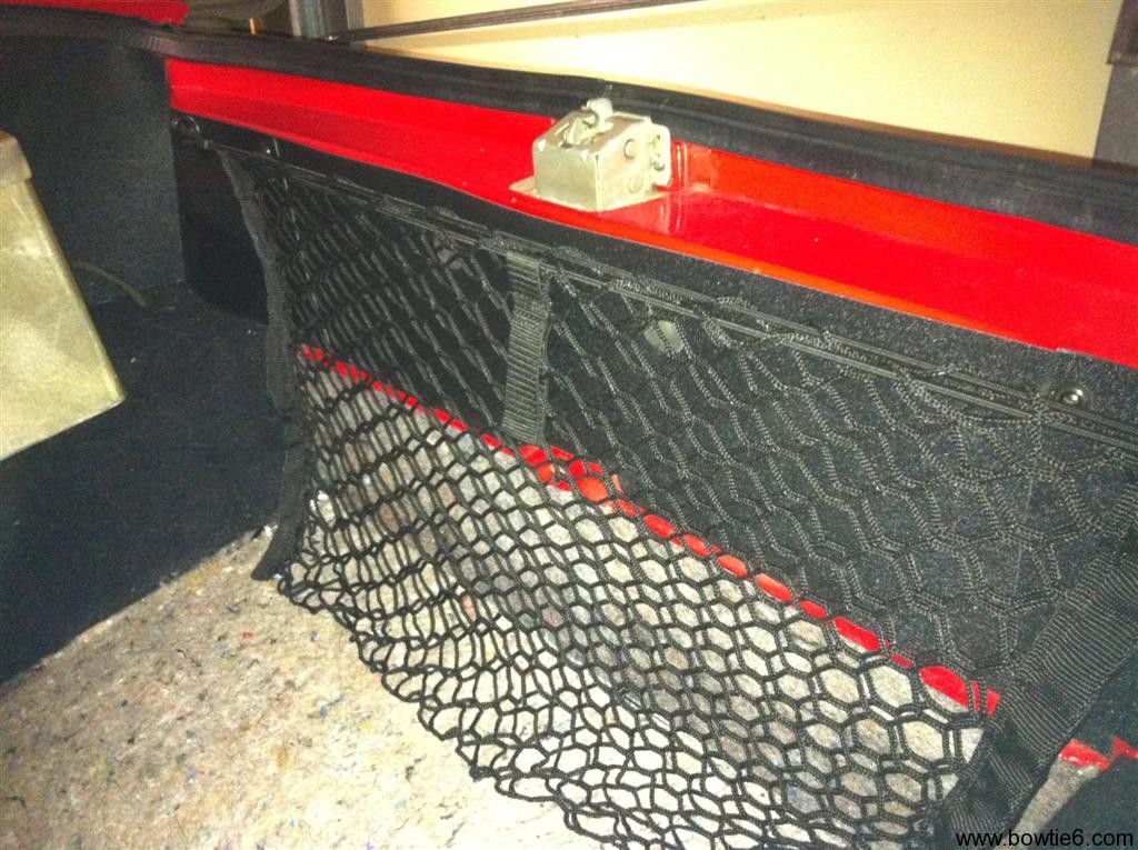
The pièce de résistance in the cargo net.  I know, not “original” but it is not only very attractive but also extremely useful.  Since I don’t have to carry a spare TR6 worth of parts and a full compliment of wrenches, I have a bit more room than the average British car owner ever dreams of having.  For example, when I make a quick run down to the grocery store I can put bags in there and the contents won’t go all over the place.  Similarly when going to a car show, I’ll put odds and ends in there.  A quick search on eBay will yield you a plethora of suitable options; that is where I found this one.  There is an elastic strand at the very top that holds the thing in place and on either side are two special hooks that catch the ends.  You can see that in the first picture above.

Here is the battery box.  This is all aluminium and there is a Red Top Optima dry cell battery inside.  These batteries are not cheap, but offer many advantages over all the others.  I’ve had this one for several years now and it is as strong as the day I bough it.  You can see in the background the same plastic material I used for the rest of the liner.

On closer inspection you can see two more details…

  1. To the right of the box is a thick cable.  This is the same kind of cable used for leads on a Miller TIG welding machine.  In this case, this is the heavy ground cable clamped to the negative side of the battery.  This cable goes through a rubber insulated opening in the floor of the trunk and the end is securely bolted to the frame.  This gives the body a hard ground.  Up front, in the engine compartment there are two more similar cables.  One is tied directly to the engine (grounding the Ecotec) and the other is tied directly to the body (making the body ground too).  Without solid grounds your electrical system will fail.
  2. On the left of the box you can see a silver plate.  Bolted to it are two circuit breakers an three relays.  The circuit breakers feed the relays which in turn supply the a) fuel pump, b) stop lamps and c) reverse lights with power.  I’ll have more about bowtie6‘s electrical system in a later issue.

And there you have it.  One thing about doing work like this is to think outside the box.  With so many modern materials available it is a shame not to use them.

ECOTEC Fuel System – Part 2

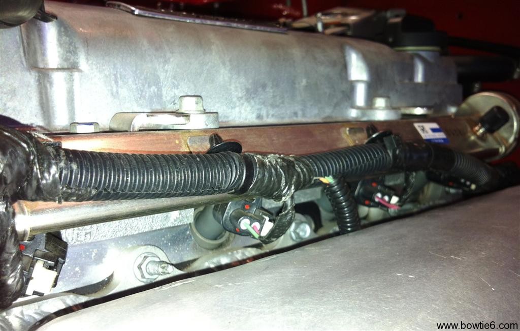
Just a followup on yesterday’s post.  This time, a few pictures of the engine side of things.  Here is the fuel rail, on the extreme right is the fuel inlet and below the rail itself is the loom holding the wires for the injectors.

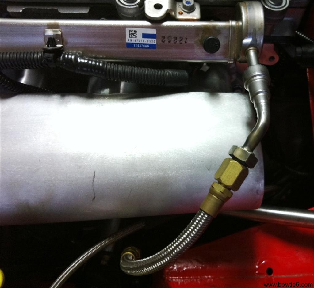
Here is the fuel supply side.  This one took some doing.  At the extreme lower side (close to the car’s body) you can see the end of the braided line.  That end has a crimped fitting that screws into the stainless steel line feeding fuel from the rear of the car.  That stainless line is held in place by these really cool brackets that unfortunately are not seen.  I’ll have to post about them in a later installment.  At any rate, on the other side of the braided line is another fitting that screws into the solid line shown below.

That line is basically a factory unit that has been modified bigtime.  Ther is a threaded fitting that was silver soldered that allows the braided line to be screwed on.  The reason why this had to start as a factory item is because of the special connector on the side of the fuel rail.  That one clicks into the tube sticking out of the fuel rail.  There is a special took that is used to take that out, by the way.

Finally, on the fuel rail itself you can see the Schrader valve (that black dot) on the right.  This is where you can tap a fuel pressure gauge into, for measuring fuel pressure.  This is all factory items.

Finally, this is what the injector underneath the fuel rail looks like. The rail looks rusted but that is only reflection from the red paint from the rest of the car.  In reality it is quite shiny.  This is number 2 injector going into the head.

And this keeps the engine alive and kicking!