Category Archives: Intake

Ecotec Intake Manifold Upgrade

Been a long time since I’ve done any work on bowtie6.  This little car is just like a trusted Timex watch – it takes a beating and keeps on ticking.  This weekend I installed an upgrade:  the other day, I came across a vendor that offered a phenolic intake spacer for the Ecotec.  The advantage of a phenolic spacer is to help reduce heat transfer from the head into the intake manifold.

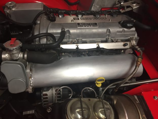
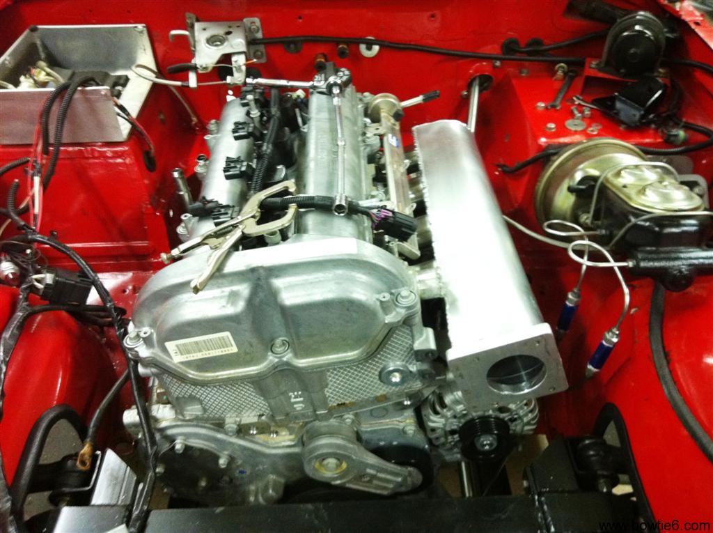
The intake manifold my cousin Jim made when we installed the Ecotec in bowtie6 is all aluminum (in case you want to know more about it, here is the link to a previous article with details about the custom intake).  We did this because the original composite intake from the Solstice was just too large and would not fit because the steering shaft lives where the factory intake is attached to the head.

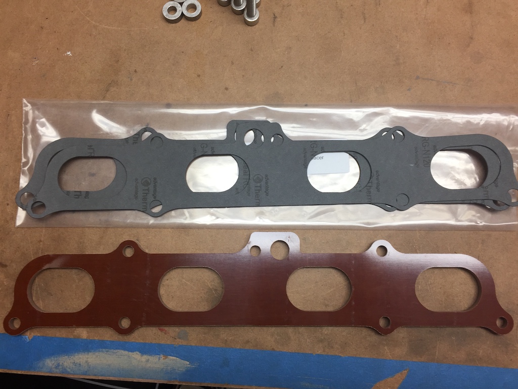
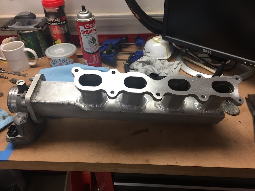
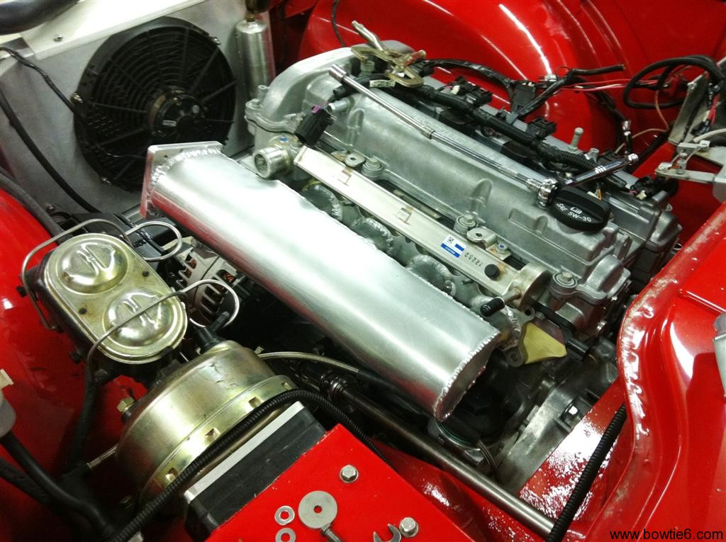
You can see the intake in today’s featured image above, and as you can imagine it gets a bit warm.  I suppose the amount of time air hangs around the intake manifold is minimal, but any improvement would be helpful.  So, I sent the $99 plus shipping for the phenolic spacer and a couple of days later, one of the brown trucks delivered this:

The phenolic spacer matches perfectly the GM intake manifold plate Jim used to build the custom intake and is exactly 1/4 inch wide.  The “kit” comes with new gaskets and several replacement bolts.  Sadly the bolts did not fit the head of the LE5.  When I trial fitted all this, I noticed the factory bolts were about 1/4 inch too short (duh!), so I had to go find replacements.  Fortunately the local NAPA store not far from home had them in stainless, no less.  Torque settings on these bolts is not high, so the NAPA bolts worked just fine.  Not bad for $8 and change.

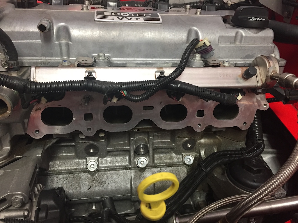
Taking the bolts out was a job!  There is just no room.  But, with a little patience and a few curse words, the manifold finally came out.  I remember I had used RTV on the original metal gasket and was left with quite a bit to clean up.  This is the intake manifold minutes after I had removed it.

And here we have the other side.  I had to remove the valve cover breather hose and the coolant hose.  You can also see the alternator is still bolted to the block (more on this later).After a little elbow grease, the head and the intake came clean.  From the mess in the the photos above, we have this:
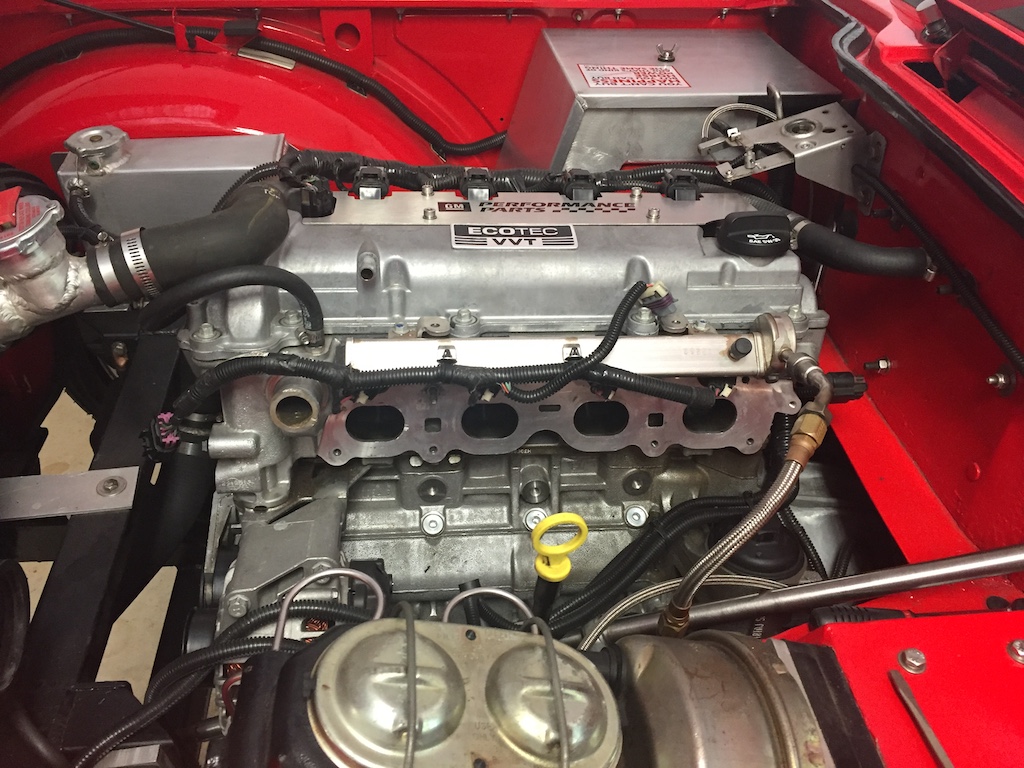
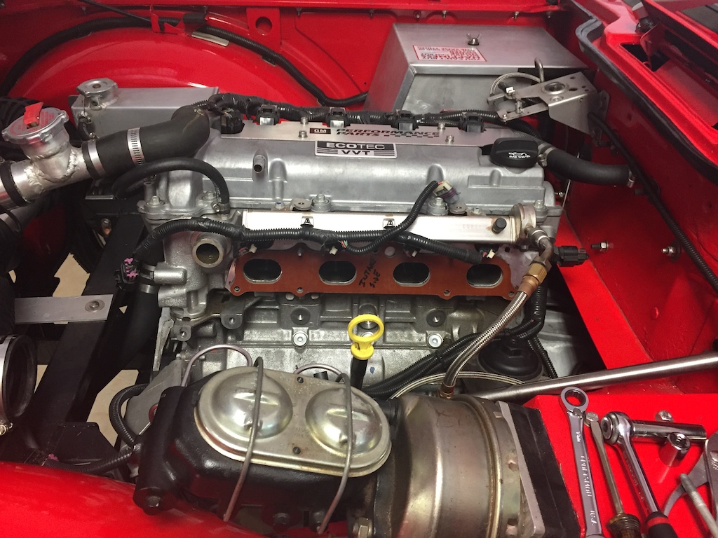
Remember I mentioned the alternator being mounted?  Well, after trial fitting the whole affair, I found there was no way in hell the bottom bolts could be reached without dropping the alternator.  Here is what the phenolic spacer looks like in its new residence…

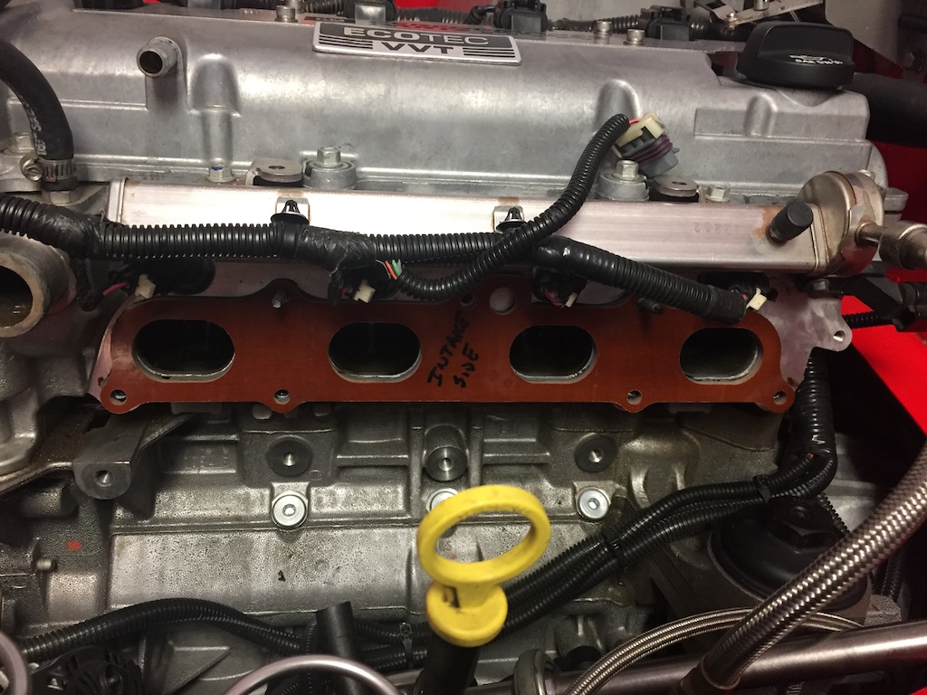
And here is a closeup…

I had to mark the spacer with “block side” and “intake side” so I could line up the new gaskets in the right direction.  Yes, they have a “side” – you can see that in the first picture above.

Then, the fun part:  getting it all back together.  As I mentioned the new bolts are about 1/4 longer, so it took some fiddling to get them lined up just right.  I had to pay close attention to the gasket orientation and used a bit of gasket adhesive on the gasket face next to the block and intake.  I left the faces that come in contact with the phenolic spacer dry because I did not want to risk damaging the phenolic material with the gasket adhesive material.
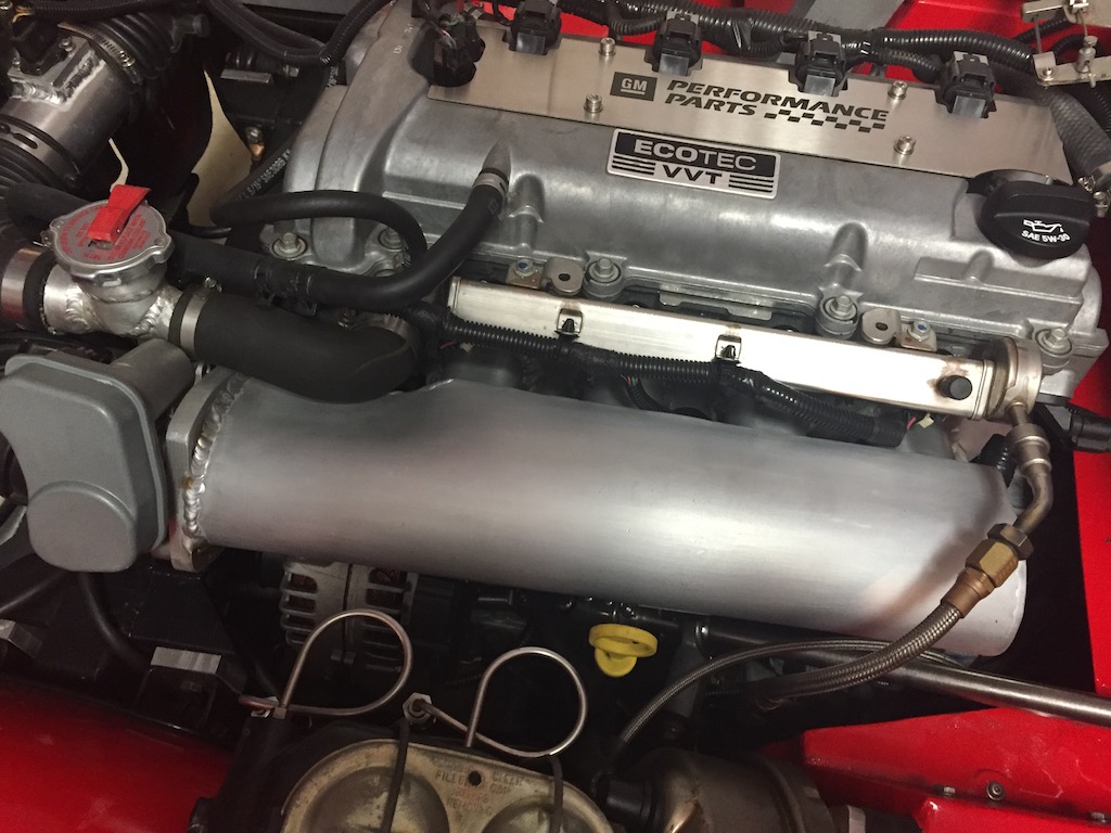
All that hard work, and you can’t even see the spacer!  So much of bowtie6 is like this too.

And so, it is time to start the engine and go for a ride.  But, we can’t have a good automotive project without the proverbial “oh shit” moment…

  • gaskets lined up – check –
  • bolts all accounted for – check –
  • no extra parts (yeah!) – check –
  • wiring connectors plugged up – check –
  • alternator properly bolted – check –
  • serpentine belt on – check –
  • engine coolant hose – check –
  • valve breather hose – check –

Get the keys, jump in and hit the ignition button.  Nothing.  Engine turned and turned, no fire.  Strong smell of fuel.

Damn!

I retrace steps.  Had to be something simple.  Turns out the plug for the injector harness is the exact same size as the one for the electronic throttle body.  I had them switched.  No wonder.  After swapping the electrical connectors, I tried to start the engine again.  This time, a cloud of smoke came out the exhaust – she was pretty flooded so I decided to let the engine idle for a few minutes.

Finally, backed the car up and went for a short drive.  I noticed no seat-of-the-pants improvement, but I did touch the intake when I returned and it felt much cooler.  I have no idea if all this is going to make a difference but there is no big investment here.  And yes, I would agree if you say that heat will still make it into the intake just by heat transferring through the bolts.

We shall see how this little experiment goes…


Intake Repaired

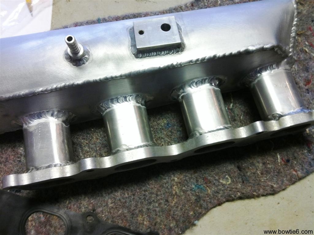
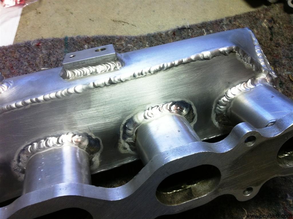
After careful inspection and a thorough cleaning, the intake was repaired by my cousin Jim.  We did find another small crack that had developed on the outside of the plenum – not a leak, but more of a stress crack.  At any rate, with some new weld beads, the runners are all repaired now.  This is what things look like, after the repairs:

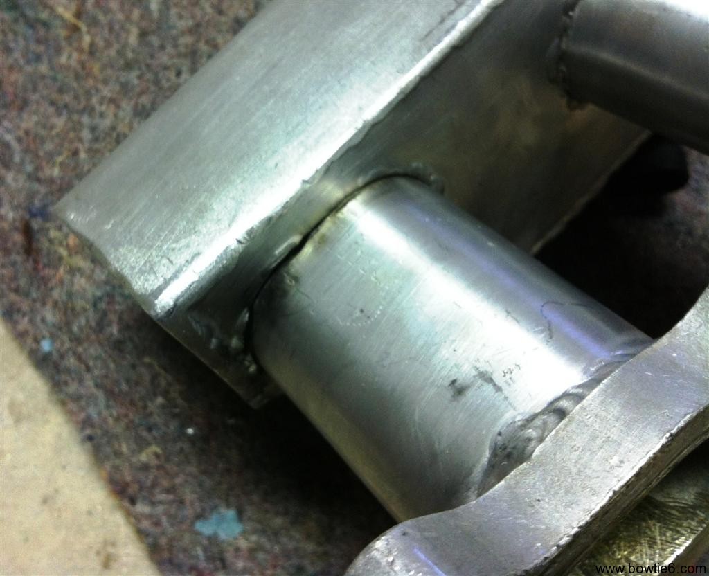
Here is a closer look at the affected area:

The face of the flange was found to be ever so slightly not 100% flat.  With a little machining, it is now level and flat.  I started putting this all back together last night.  Should have it all running today…


Backfire!

Looks like 2011 ends in a bang.  Literally.

Yesterday morning the sun was out so I decided to take bowtie6 to work.  Unfortunately, I did not press the “Start” button long enough, the engine turned for just a split second and backfired when I let go of the button.  I’ve had this happen twice before with no serious consequences but this time, we had a problem: the “bang” cracked the intake.

There is nothing wrong with the design of the intake or with anything else.  This was my mistake 100%.  I just call this a risk of running non-factory parts.  The new intake is all aluminium; this is what the intake looks like:

We had to make this intake up because there is no room for the original plastic intake.  Actually there is, but it would have required the steering column to be relocated bigtime and it was just not worth the trouble.  The intake you see above is made in several pieces.  The flange that bolts to the head came from GM Performance Parts and is water jet cut aluminium.  This all has to be made in pieces and welded in place as such.  The four intake runners are aluminium tubing, cut and bent to fit the oval ports on the GMPP flange.  They were welded to the flange from the outside otherwise there would be a lot of machining to make the flange perfectly flat again.

The runners then were fitted to a flat piece of aluminium which made the intake side of the long plenum on the top.  There was a bead ran on the inside of that plate.  Then, the rest of the plenum was shaped and welded in place.  The seams were filed smooth and it all looks like one solid piece.  Finally a flange was made and welded where the throttle body gets bolted with four screws.

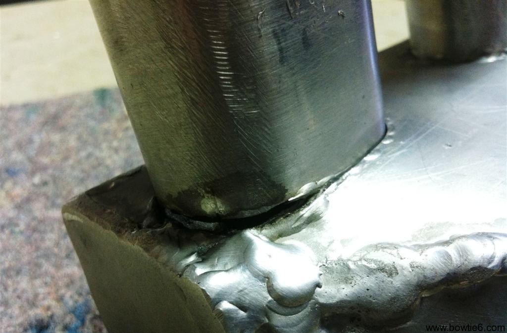
All good, except that the four runners ended up with a delicate bead around them, on the inside of the intake plenum.  So, when the backfired occurred it caused the seam on number 4 runner to assplode.  Take a look:

Obviously, it doesn’t take much for the thing to have a major vacuum leak and cause the engine to fail to run.  Needless to say, with this crack RPM’s went through the roof!  One interesting thing about all this is the ECM was smart enough to figure this out, and basically shut things down.

The outside of the runners needs to be welded again (duh!).  Had we not had the backfire, this would have not been a problem.  The seal has been flawless but unfortunately the thing just could not cope with the force of the assplosion.  As you can see, the intake has been removed and will be welded back today.  I hope to be back on the road hopefully tomorrow.

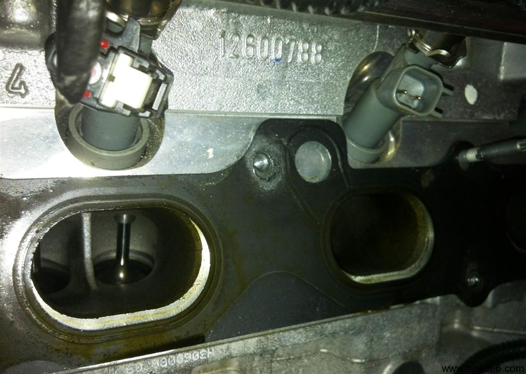
Here is a picture of engine-side of things:

Sorry for the picture being so dark, but you can see there is not much distance between the intake valves and the actual intake itself.  Not at all.  Also, the gasket seems out of place because it is not pushed all the way up against the head – in reality it fits perfectly with the intake opening.

No worries though – this should be a quick fix…  🙂


ECOTEC Drive by Wire

All modern GM engines (LSx’s, Vortec’s, Ecotec’s, etc.) use the so called “drive by wire” or “fly by wire” throttle bodies.  Long gone are the days of actuating the throttle butterfly by mechanical means – ie, a cable – from the accelerator pedal to the throttle body.  Instead, the throttle butterfly is now controlled by a servo motor actuated by inputs from an electronic accelerator pedal attached to the ECM.  If you Google any of these terms, you will get plenty of info on how it works so I won’t go into the details.  This hangs up a lot of folks doing conversions and they end up using a throttle body with a cable.  We did not want to go that route.  What I do want to show here is how we solved some of these problems on bowtie6 while still retaining all the electronics.

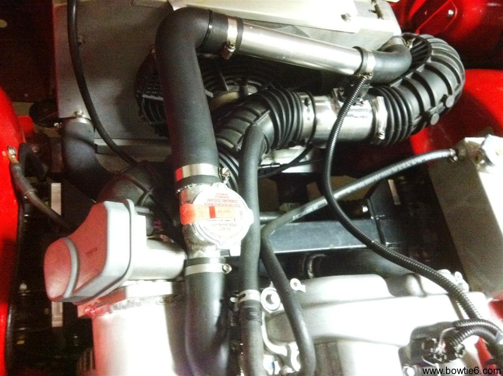
The following pictures show what the throttle body looks like.  Since we are running a completely different intake manifold from the Solstice, the throttle body is bolted on a special flange on the new intake.  We could have used the plastic intake, but that would have been a major hassle with the steering mechanism.  In front of all this is flexible rubber tubing recycled from the Solstice.  The silver tube midways is the special housing for the MAF sensor and ahead of that (hidden by the radiator and ahead of the rubber bend tubing) is a K&N air filter.  On bowtie6, the air filter sits ahead of the radiator, right behind the factory grille allowing the coldest air to be pulled in.  However, this all comes at a price:  the MAF must be re-calibrated because of all the bends in the airflow.

This is what the whole shebang looks like…

Here is a closeup of the throttle body…

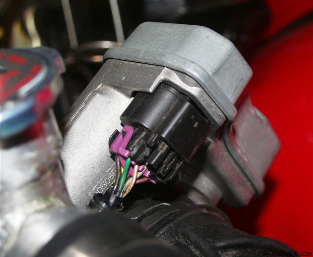
This is the stock throttle body as found in the Pontiac Solstice/Saturn Sky.  The grey plastic cover hides the stepper motor and the rest of the mechanism that opens and closes the butterfly activated by the ECM.  Here is another picture from the back of the throttle body showing the connector plug with the wires coming from the ECM.

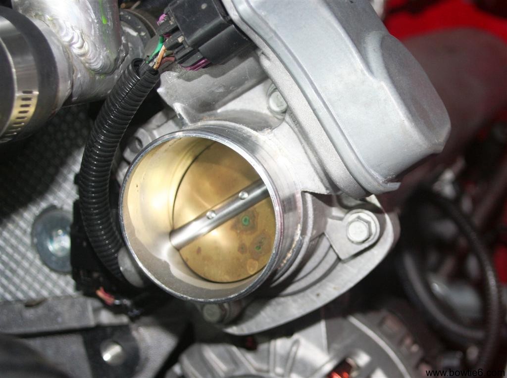
Finally, here is what the inside of the throttle body looks like.  I reckon this all could eventually be fully polished, however I have doubts on how great that idea would be and whether there would be any benefit in that.  At any rate, it is what it is…

As you can see, there is no cable.  This is all controlled electronically.  Right before ignition, the engine does a “test” of the throttle body and yes, there is a split second delay.  If you pay attention, one can actually hear the stepper motor in the throttle body opening the butterfly to WOT and then back to the closed position.  Then ignition occurs.

If you are looking at all this and wondering where the traditional Idle Air Motor is then you are correct:  it is not here.  Idle is handled by the ECM and TPS.  From there, the butterfly opens to control idle.

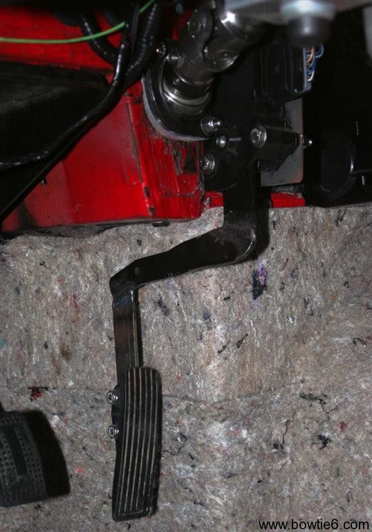
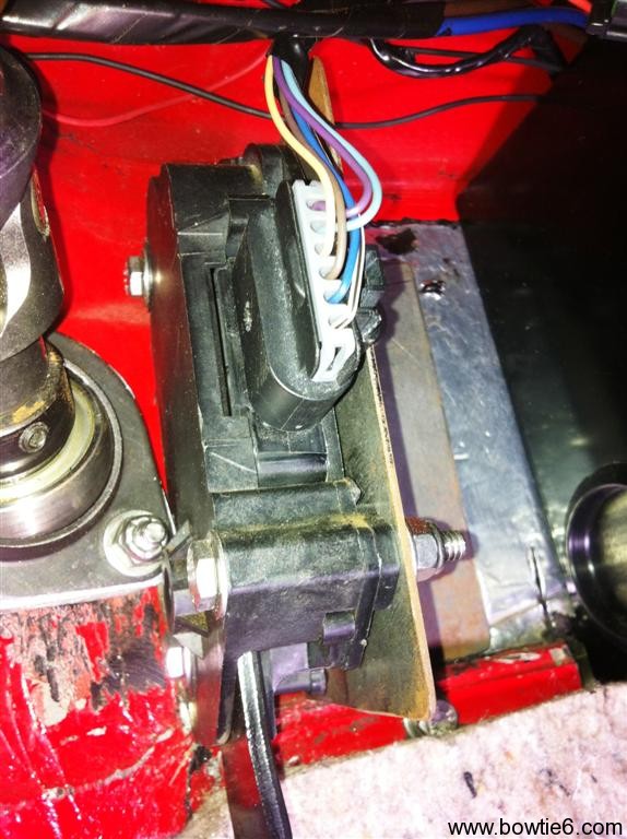
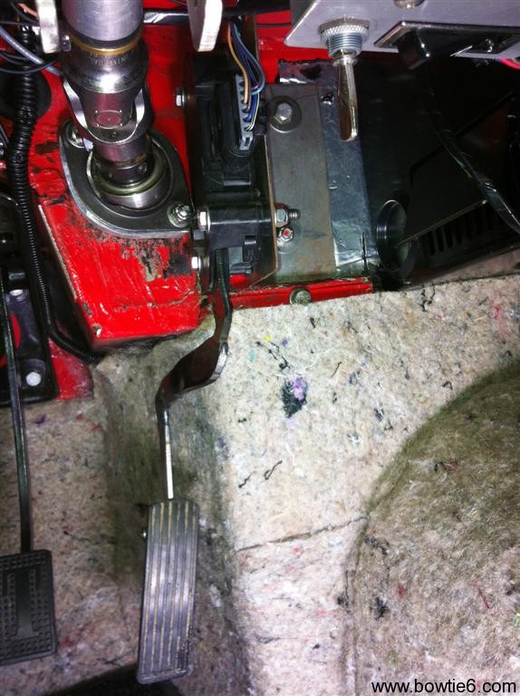
Controlling all this requires the special matching throttle pedal.  Here is where things get interesting.  There are quite a few versions of these throttle pedals.  For example, Vortec engines have a certain version, GTO has another and Vette’s have yet another.  Along with that, some are all plastic, others are plastic with metal arms, some have 6 wires and some have 8 wires.  In our case, we used a throttle pedal used in the 2.4 Ecotec powered HHR.  The advantage of this pedal is that the actuator arm is metal, and thus can be cut and shaped to fit the location where it is mounted in.  This is what the one in bowtie6 looks like:

Sorry for the boring gray background (this is a sound insulating material glued to the Dynamat Extreme prepared body) but thought it be best to take this picture before I install the black carpet.  Otherwise we won’t be able to tell squat of what this looks like.  Some things to keep in mind about what you see above:

  • The pedal is still a little “crude”, if you will.  This is version 1.0 of the pedal.  So far even though it works perfectly there is some issue with the exact angle of the plastic pedal itself.  As you can see it is still a bit too straight.  I am planning to fine tune it by angling it a bit – the top needs to be brought down a little and the bottom needs to come up.  I just need to make up my mind on how far to make the angle.  It is also a bit long.  As you can see the top is rounded somewhat.  I need to make the bottom rounded as well.
  • The “travel” takes some getting used to.  This is a small compromise but this has to be retained because this is the way the ECM is expecting the signal to be sent.  If you look closely, there is a plug at the top with some wires going into a housing.  This is where the potentiometer that translates pedal movement into a signal resides.  This is what tells the ECM what throttle angle is being requested.
  • Looking at the picture above would lead you to believe the metal “arm” hits the red body of the car at the top, right?  Nope.  The travel is not great at all and the arm does not touch the body at WOT.  I also own a 2.4 Ecotec powered HHR and the throttle travel there is equally short.  However, believe me – this is not a problem at all when driving the car.  The throttle has the same “look and feel” as a mechanical system does.  It just takes a little getting used to.

For those of you considering an Ecotec conversion, this is going to be a very important issue to figure out.  Like I said before, there are many different varieties of thottle pedals.  I have read where there are some that are actually meant for the V8’s.  Once you settle on the correct pedal to use, placement will require some adjustments.  Mine is close but not quite 100% perfect yet.

There is yet another alternative and that is to use a Lokar fly-by-wire system.  I think these were introduced at SEMA earlier this year.  I have done some reading about them but I have not seen one in person and have no idea how helpful it would be.  On the downside too is the price – they are quite price.  The stock GM stuff can be had for a few bucks at your junkyard or from auction on eBay.

bowtie6‘s ECOTEC Custom Intake

Lots of new progress to report this weekend.

  • Solid axle & Posi-Traction differential – check
  • Disc brakes (on all four wheels) plumbed with hand-formed stainless lines – check
  • Handbrakes using original TR6 cables – check
  • Wilwood proportioning valve – check
  • ECOTEC using custom/factory mounts – check
  • Fourth Gen Camaro hydraulic clutch – check
  • AISIN 5 speed gearbox on custom mounts – check
  • Tilt steering on a Triumph TR6 (I’ll have more on this later) – check

And the pièce de résistance for today’s post:  a hand formed aluminium intake.

The factory ECOTEC comes with a very intricate and quite impressive composite intake manifold.  The thing has a very unique shape, with a convoluted “S” shaped intake that splits the aft of the throttle body into four runners feeding each intake port.  With the longer runners, lower torque is improved.  Too bad we could not use this intake.  Why?  In the TR6 the steering shaft is in the way and the front fender would just not allow the factory intake to fit.

So what is one to do?  Answer:

GM makes these cool plates for the exhaust and intake ports that are intended for exactly this type of application.  The exhaust plate has already been used to make the exhaust headers on bowtie6 (if you haven’t seen that, CLICK HERE).

Now the intake plate along with my cousin Jim’s serious welding and fabricating skillz yields the following:

The intake is fitted for a trial fit and the all-aluminium body is yet to be fully finished.  Here is another set of pictures:

The photo above shows the front section of the custom intake.  The fly-by-wire throttle body will bolt to the flange on the front.  Not shown on the picture above is the port for the MAP sensor as well as the bung for the vacuum line going to the brake booster on the right.  Which, by the way is from a Vette along with the mastery cylinder.  What are those blue thinggies on both of the brakes lines?  Hmmm…  Wonder what that is all about??

Last but not least, another view this time towards the front of the car.  Yes, that is an all aluminium radiator up front.  The fan is SPAL (the same kind used by the boys from Maranello) mounted on an aluminium shroud.  Why the shroud?  I covered that in my original explanation in my original website.  Want to read about that?  CLICK HERE.

Pretty cool, huh?