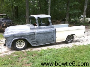
 Back in the mid 50’s, Chevrolet decided to build a unique pickup. Along with the knowledge they learned from the Corvette they made a pickup with a fiberglass-sided bed. This is known as the Cameo. I won’t go into much detail about the history of it (you can Google that), suffice to say they are rare and one belongs to our friend Barry A.
Barry brought the frame over to my cousin Jim’s shop with intentions of making it a reliable modern truck with a very special vintage appearance. An modern Chevrolet Vortec engine (an LSx) will propel this Cameo to match its awesome good looks. It has taken some time, effort and resources but the Cameo is starting to take shape. Once again my cousin Jim has done some pretty awesome things and I wanted to share some of them here.
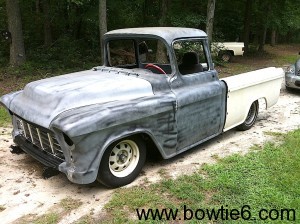 As you can see in these two pictures, the Cameo is together and running.
The frame has had quite a bit of work including bespoke engine and transmission mounts. The front suspension contains all new components such as a A-arms, modern steering rack, coilovers and disc brakes. The rear axle is from a late model Ford Explorer including a positraction rear end, disc brakes and coilover suspension. Jim modified the rear axle with control arms and since space was at a premium, it includes a Panhard bar.
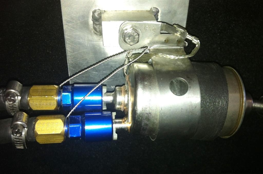
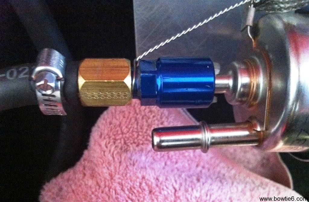
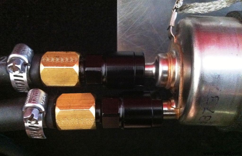
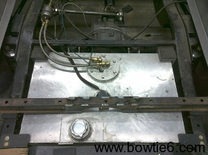 You can actually see the Panhard bar at the top of the picture on the right. Also here you can see the custom made aluminium fuel cell that Jim made special to fit the frame. It is mounted on special plastic mounts. The fuel filler neck is also custom as well as the fuel level sending unit and fuel pump housing. That is on the big round disc on the cab-side of the tank. This is all plumbed with braided steel lines and attached to an LSx fuel pressure/filter housing. Since the LSx is a returnless system, from the other side of the fuel regulator a line goes forward to feed the LSx engine. Finally, thanks to that space restriction, two large exhaust mufflers sit below the cab and will eventually dump on special pipes shaped to dump ahead of the rear tires.
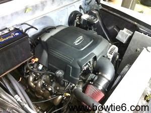 What powers the Cameo? Why an LSx, of course!! This engine came from a 2010 Chevy truck as you can see on the picture at left. Jim made all the special mounts and details you see in this picture. The two silver boxes on the extreme top right house the electric fan controller and the ECM. Jim also made the wiring harness – we don’t buy aftermarket harnesses, instead ours are modified in-house and are sized to fit the requirements of the build. This is all housed along with numerous relays, circuit breakers and fuses in the long silver box next to the controller. Since Barry’s truck will have a fully functional A/C system you can see the special hoses routed under the battery feeding the A/C system inside the cab. If you look closely you can see the special stainless headers – yes they are stainless and look awesome in person. Keeping things cool is a special aluminum radiator ahead of the K&N air filter on that trick 90 degree elbow Barry sourced special for this build.
In order to get the engine running we had to do a basic tuning with HPTuners to remove the VATS as well as other issues that prevented the engine from running. Furthermore this is a 2010 engine and as such it comes equipped with Displacement On Demand (DOD) as well as Variable Valve Timing (VVT). For now, we have electronically disabled DOD and kept the VVT. We still need to do some more MAF calibrations as well as fuel and ignition mappings. The engine is also running a Transmission Control Module (TCM) in order to run a 4L60E transmission. Barry opted to run this instead of the six speed gearbox originally fitted to this engine.
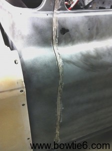 The following pictures will demonstrate some of Jim’s sheet-metal skillz. 🙂
How do you get body-fit on a mid 50’s vehicle to compare with modern cars? Well, it takes special tools and ability. As you can see on the picture to the left, there is a shiny strip on the edge of the door. Basically Jim has added material to the edge to extend the door skin and thus achieve a high level of consistent “gap”. This has all been carefully filed and will require a small amount of filler (if any) to get perfectly straight.
The next picture shows some more tricks!
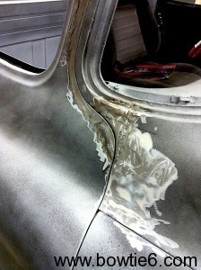 The original Cameo door had a squared-off edge on the panel below the windshield. As you can see here, similar to a plastic surgeon Jim has re-shaped the door’s edge to create a curved shape that matches the curvature of the rest of the door along the roofline. This yields are much more elegant fit and will only noticeable by someone very familiar with the door shape of a Cameo. Not only was the door shaped this way, but the body had to be altered to match the new curvature.
All in all, the final result is very nice indeed and gives the door a very finished look.
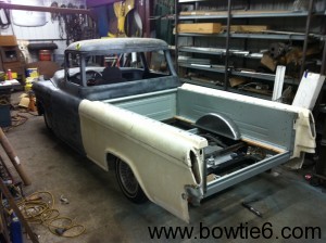 Lets talk about that special plastic-fantastic bed, shall we?
This picture shows what the outside skin of the bed looks like. Yes, that is mid 50’s vintage fiberglass – just like the one used in Vettes of the day. There is a steel liner where the fiberglass side pieces bolt on to. There is some damage that will need to be repaired but overall it makes for a very special and unusual looking truck bed. If you look closely on this picture you can see a custom tubbing of the rear wheels. You guessed it – Jim made that from scratch!
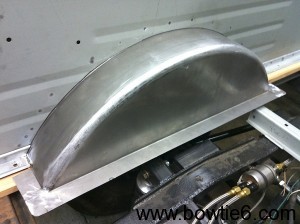 By using the Pullmax machine, Jim was able to create these special tubs. They fit the curvature of the bed opening perfectly and give a very professional, almost “factory” appearance. They have been welded in place against the inner bed wall and should compliment the look of the bed once the wood floor is fabricated.
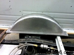 Here is another point of view of the rear wheel tub. The curvature is almost perfect and you can hardly see where the different parts were welded and blended together.
The final photo below shows the nose of Barry’s Cameo. You can see the special A/C condenser mounted behind the chrome grille and ahead of the radiator. Jim mentioned the grille fit like a glove but some adjustments had to be made in order to center it and make it look perfect. Below the grille will be either a roll-pan or chrome bumper. Barry and Jim are still working on those details.
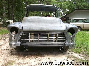 These pictures show a huge amount of work both from Barry and Jim on making this a reality. As I mentioned previously, the Cameo is alive and well. When the LSx was first fired up, it barked a little but with some very basic tuning from yours truly the engine came to life. Barry is currently doing the necessary paperwork to have the truck street-legal and the plan is to get the wiring done so the truck can be properly sorted out on the road.
Oh and just in case you were wondering… The Cameo is not Barry’s only vintage Chevy product. Take a look at my previous story (click HERE) to see the Cameo’s future stable mate: the blue and white Shoebox Chevy… Pretty sweet, huh? 🙂
In closing: well Barry, I know you are reading this blog so please add a reply in the feedback section and give us more details!!!!
